New energy automobile charging pile

A technology of new energy vehicles and charging piles, which is applied in the direction of electric vehicle charging technology, charging stations, electric vehicles, etc., can solve the problems of easy wear and tear of charging lines, fixed positions, and easy safety accidents, so as to prevent easy wear or accidents Accidents, time saving, and work efficiency improvement effects

Active Publication Date: 2018-11-06
嘉兴沃瑞科技有限公司
View PDF6 Cites 3 Cited by
  • Summary
  • Abstract
  • Description
  • Claims
  • Application Information

AI Technical Summary

Problems solved by technology

Charging piles are supporting facilities for new energy vehicles and are carriers for charging new energy vehicles. However, traditional charging piles have a single structure and a fixed position, and the position of the charging gun cannot be adjusted according to needs. The long charging cable is easy to wear and tear during use and it is not easy to put it back in place, which is prone to safety accidents

Method used


Image

  • New energy automobile charging pile
  • New energy automobile charging pile
  • New energy automobile charging pile

Examples


specific Embodiment approach 1

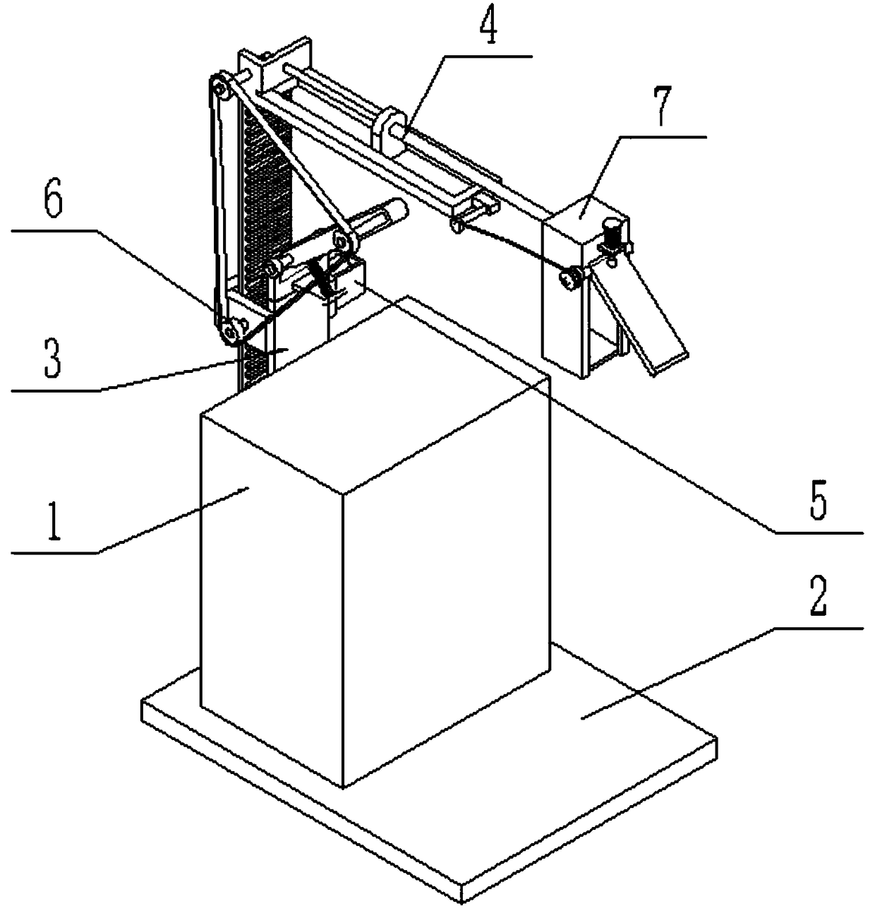
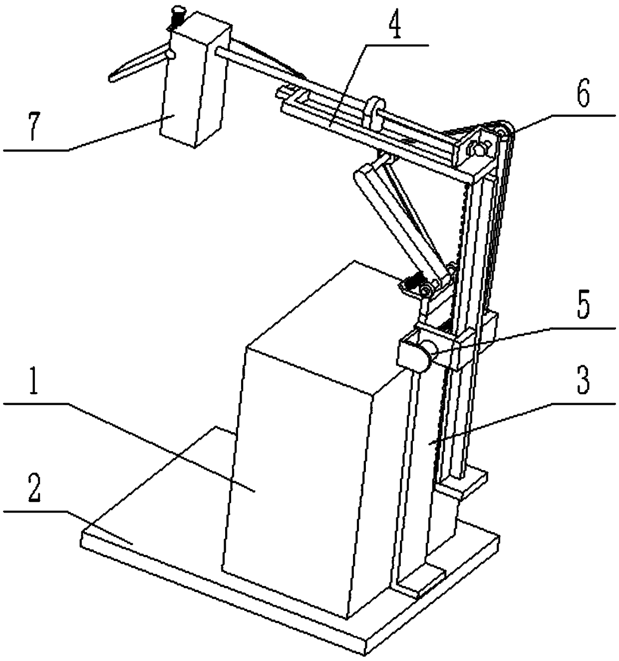
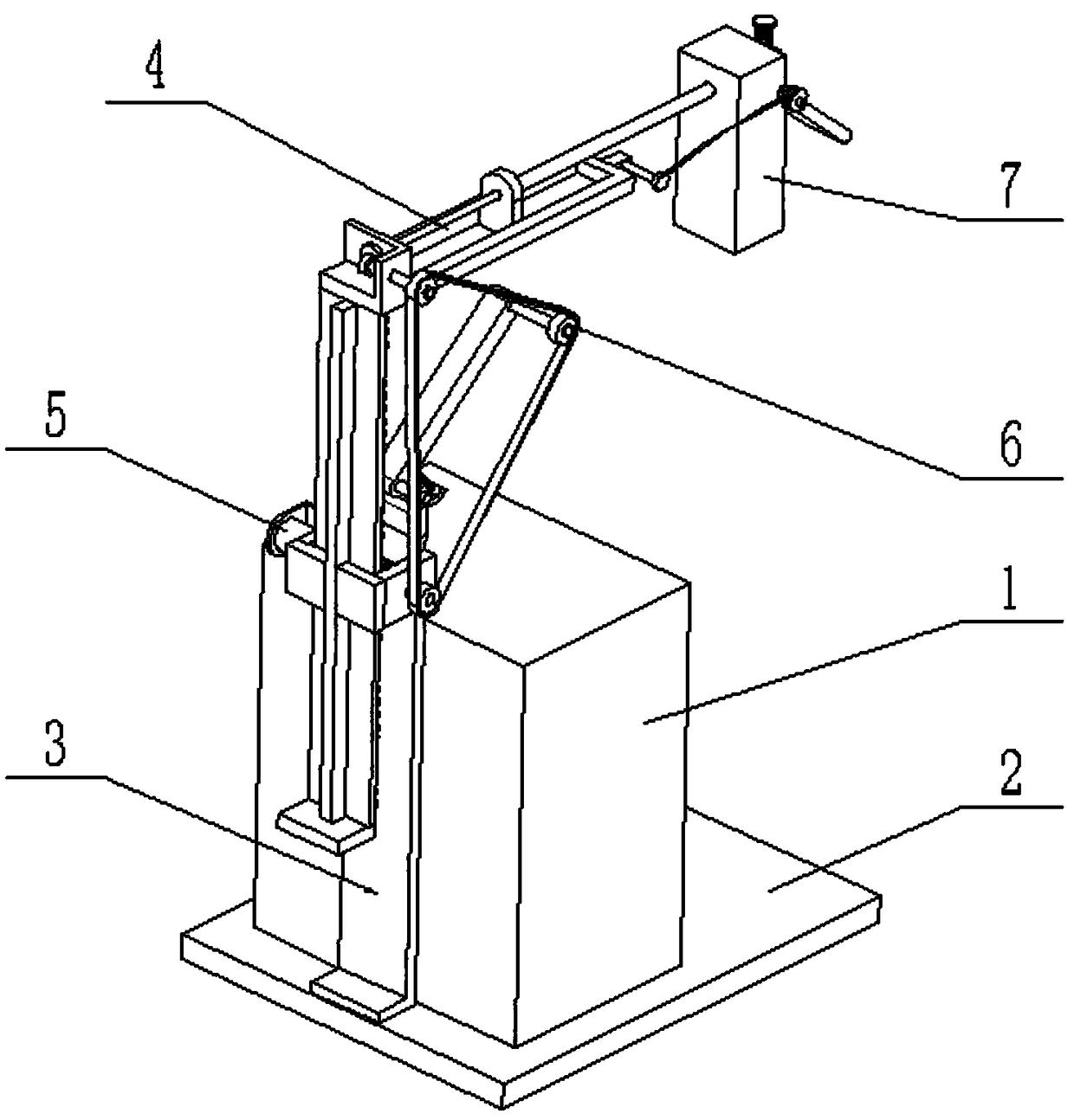
[0024] Such as Figure 1-10 As shown, a new energy vehicle charging pile includes a charging pile body 1, a base plate 2, a lifting bracket assembly 3, a telescopic horizontal frame assembly 4, a drive control device 5, a tension transmission wheel assembly 6, and a charging gun storage box assembly 7 and the charging gun body, the charging pile body 1 is fixedly connected to the base plate 2; the lifting bracket assembly 3 is fixedly connected to the base plate 2; The upper end, the other end of the telescopic horizontal frame assembly 4 is fixedly connected to the charging gun storage box assembly 7; the drive control device 5 is connected to the lifting bracket assembly 3, and the drive control device 5 is connected to the lifting bracket assembly 3 by transmission; the drive control device 5 Connect the tension transmission wheel assembly 6, the tension transmission wheel assembly 6 is connected to the telescopic horizontal frame assembly 4; the lower end of the tension tr...

specific Embodiment approach 2

[0025] Such as Figure 1-10 As shown, the lifting bracket assembly 3 includes a fixed frame plate 3-1, an L-shaped side frame plate 3-2, a T-shaped slide plate 3-3, a rack 3-4 and a limit plate 3-5; the fixed frame The lower end of the plate 3-1 is fixedly connected to the base plate 2; two L-shaped side frame plates 3-2 are fixedly connected to the fixed frame plate 3-1, and the two L-shaped side frame plates 3-2 are arranged symmetrically on the fixed frame plate 3-1. Both sides of the frame plate 3-1; the outer side of the T-shaped slide plate 3-3 is slidingly fitted and connected between two L-shaped side frame plates 3-2; the inner side of the T-shaped slide plate 3-3 is fixedly connected to the rack 3-4; the bottom end of the T-shaped slide plate 3-3 is fixedly connected to the limit plate 3-5; the rack 3-4 is meshed and connected to the drive control device 5, and the drive control device 5 is fixedly connected to an L-shaped side frame on the plate 3-2; the upper end ...

specific Embodiment approach 3

[0026] Such as Figure 1-10 As shown, the telescopic horizontal frame assembly 4 includes a horizontal chute frame 4-1, an L-shaped shaft frame plate 4-2, a transmission shaft 4-3, a transmission bevel gear 4-4, a passive bevel gear 4-5, an external thread Rotary shaft 4-6, guide slide plate 4-7 and internal thread push-pull casing 4-8; L-shaped shaft frame plate 4-2 is fixedly connected on the horizontal chute frame 4-1; the horizontal chute frame 4-1 Fixedly connected to the upper end of the T-shaped slide plate 3-3; the transmission shaft 4-3 is rotatably connected to the L-shaped shaft frame plate 4-2 through a bearing with seat, and one end of the transmission shaft 4-3 is fixedly connected to the tensioning transmission wheel assembly 6. The other end of the transmission shaft 4-3 is fixedly connected to the transmission bevel gear 4-4, the transmission bevel gear 4-4 meshes with the passive bevel gear 4-5, and the passive bevel gear 4-5 is fixedly connected to the exter...


PUM


Abstract

The invention relates to the field of new energy automobiles, in particular to a new energy automobile charging pile. The new energy automobile charging pile comprises a charging pile body, a base board, a lifting support assembly, a telescopic transverse frame assembly, a drive control device, a tensioning transmission wheel assembly, a charging gun storage box assembly and a charging gun body. The charging pile body is fixedly connected to the base board. The lifting support assembly is fixedly connected to the base board. One end of the telescopic transverse frame assembly is fixedly connected to the upper end of the lifting support assembly. The other end of the telescopic transverse frame assembly is fixedly connected with the charging gun storage box assembly. The drive control device is connected to the lifting support assembly and is in transmission connection with the lifting support assembly. The new energy automobile charging pile is provided, the height and the horizontal position of the charging gun storage box assembly containing the charging gun body can be adjusted according to the actual requirements, a charging line of the charging gun body does not need to be toolong, and the situation that the charging line is likely to be worn or an accident is likely to happen is avoided.

Description

technical field [0001] The invention relates to the field of new energy vehicles, in particular to a charging pile for new energy vehicles. Background technique [0002] New energy: also known as unconventional energy. Refers to various forms of energy other than traditional energy. Refers to energy sources that have just begun to be developed and utilized or are being actively researched and yet to be promoted, such as solar energy, geothermal energy, wind energy, ocean energy, biomass energy, and nuclear fusion energy. New energy vehicles are gradually replacing traditional vehicles with many advantages such as energy saving, emission reduction, environmental protection and pollution-free, and are widely used. Charging piles are supporting facilities for new energy vehicles and are carriers for charging new energy vehicles. However, traditional charging piles have a single structure and a fixed position, and the position of the charging gun cannot be adjusted according t...

Claims


Application Information

Patent Timeline
Patent Type & Authority Applications(China)
IPC IPC(8): B60L11/18
CPCB60L53/31Y02T10/70Y02T10/7072Y02T90/12Y02T90/14
Inventor 梁春花
Owner 嘉兴沃瑞科技有限公司
Why Eureka
Try Eureka