Environment-friendly recycling device for chemicals in chemical tempering furnaces

A chemical tempering and recovery device technology, which is applied in glass tempering, glass manufacturing equipment, manufacturing tools, etc., can solve the problems of poor cooling efficiency and achieve the effects of short recovery time, high recovery efficiency and novel design

Inactive Publication Date: 2018-11-06
WUXI NANLIGONG TECH DEV
View PDF7 Cites 2 Cited by
  • Summary
  • Abstract
  • Description
  • Claims
  • Application Information

AI Technical Summary

Problems solved by technology

[0003] The existing device is to introduce cosmetics into the liquid tank. When the liquid tank is filled with liquid chemicals, the liquid guide tank is lifted out of the chemical tempering furnace, dripped, and cooled. When the temperature of the liquid chemicals drops to room temperature, the After the liquid turns into a solid state, the liquid holding tank is lifted out of the liquid guide tank, and the chemicals can be easily poured out by tapping around the liquid holding tank. However, the cooling efficiency is poor and impurities are easily mixed in by dripping water to cool down.

Method used


Image

  • Environment-friendly recycling device for chemicals in chemical tempering furnaces
  • Environment-friendly recycling device for chemicals in chemical tempering furnaces
  • Environment-friendly recycling device for chemicals in chemical tempering furnaces

Examples


Embodiment 1

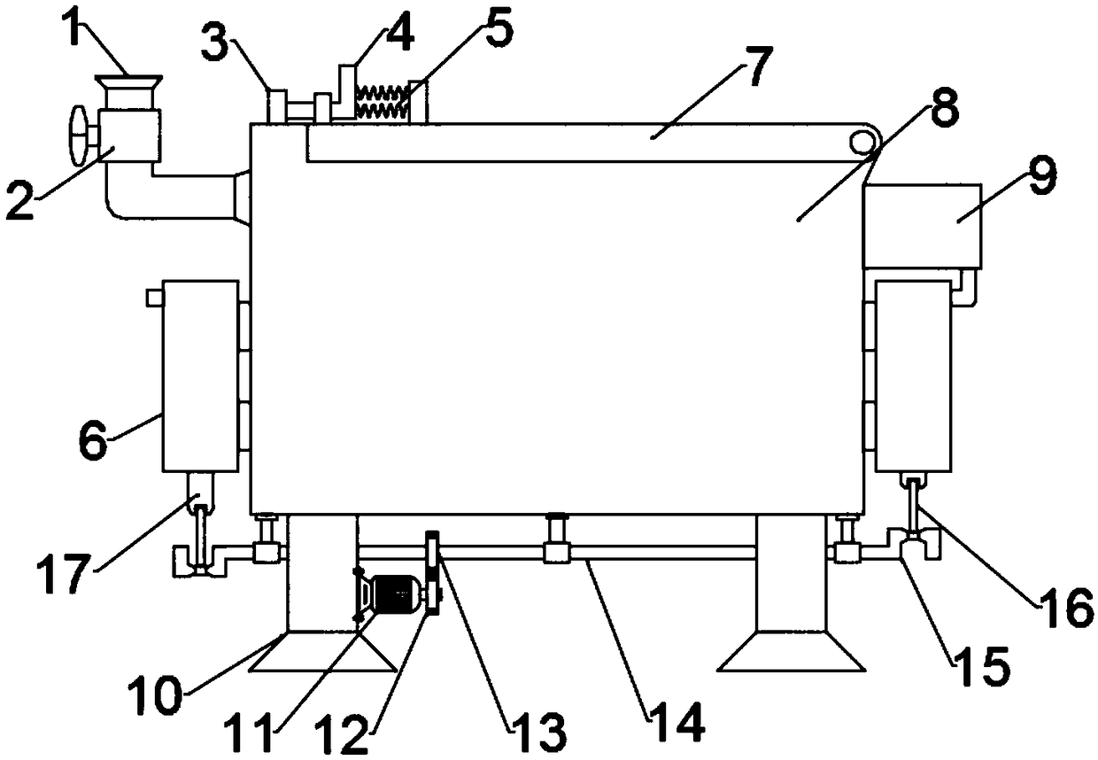
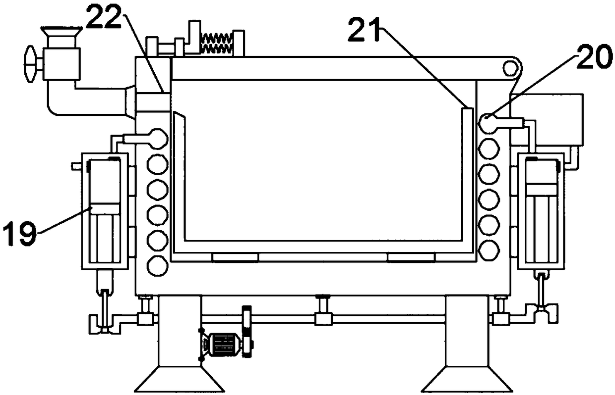
[0024] see figure 1 and 3 , an environment-friendly recovery device for chemicals in a chemical tempering furnace, comprising a recovery tank 8, a cooling mechanism and a liquid receiving tank 21; Slidingly connected, the recovery box 8 is provided with a cooling mechanism, the cooling mechanism includes a symmetrically arranged piston cylinder 6 and a cooling pipe 20, the cooling pipe 20 is wound on the inner wall of the recovery box 8, the air inlet of the cooling pipe 20 is connected to the The piston cylinder 6 on the right side is connected, and the air outlet of the cooling pipe 20 is connected with the piston cylinder 6 on the left side. A one-way valve is arranged on the inner side of the connection between the cold fire pipe 20 and the piston cylinder 6, and the inner side of the piston cylinder 6 is provided with There is a piston 19, the lower end of the piston 19 is fixedly connected with the upper end of the push rod 17, the lower end of the push rod 17 runs thro...

Embodiment 2

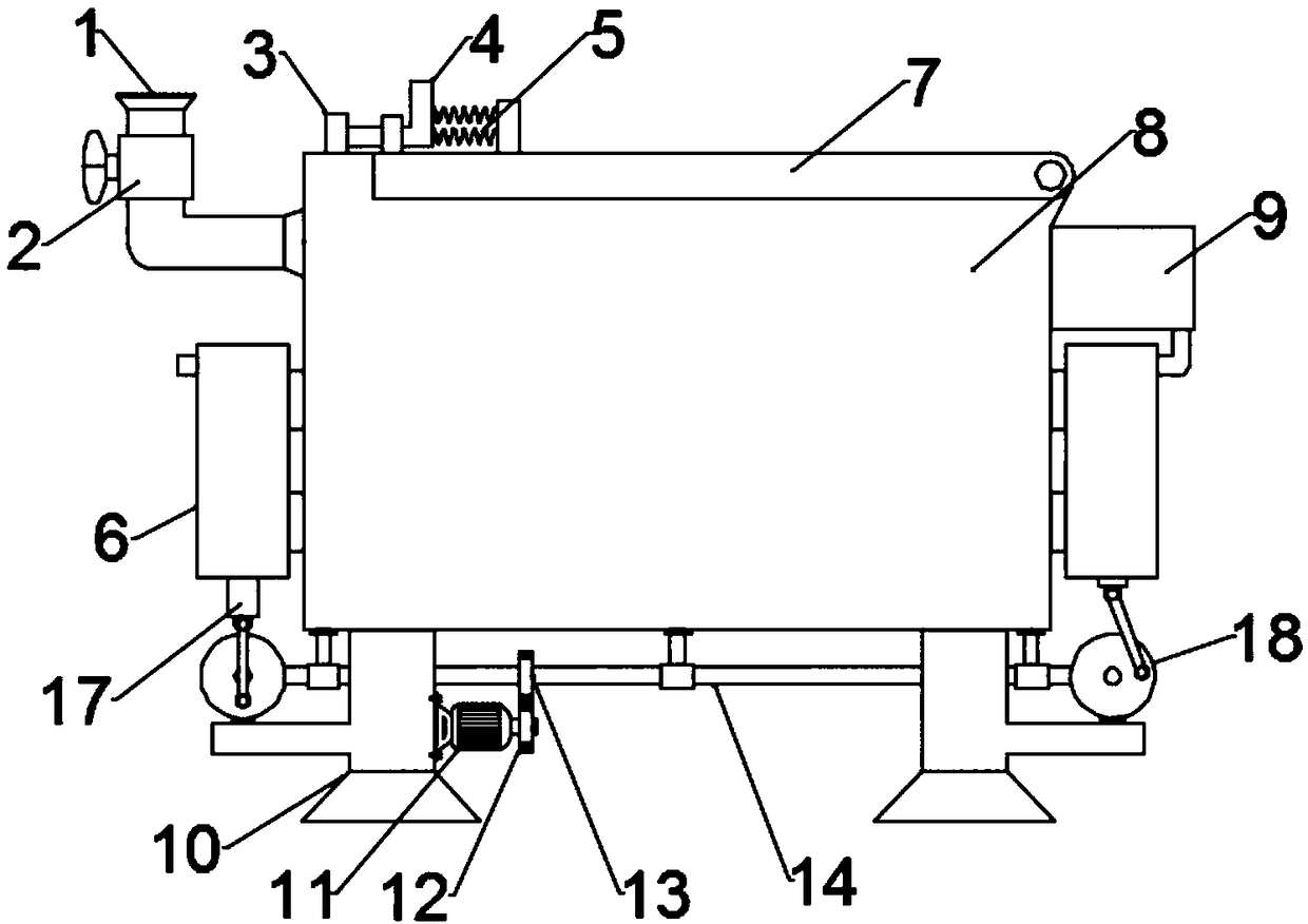
[0030] see figure 2 and 4 , an environment-friendly recovery device for chemicals in a chemical tempering furnace, comprising a recovery tank 8, a cooling mechanism and a liquid receiving tank 21; Slidingly connected, the recovery box 8 is provided with a cooling mechanism, the cooling mechanism includes a symmetrically arranged piston cylinder 6 and a cooling pipe 20, the cooling pipe 20 is wound on the inner wall of the recovery box 8, the air inlet of the cooling pipe 20 is connected to the The piston cylinder 6 on the right side is connected, and the air outlet of the cooling pipe 20 is connected with the piston cylinder 6 on the left side. A one-way valve is arranged on the inner side of the connection between the cold fire pipe 20 and the piston cylinder 6, and the inner side of the piston cylinder 6 is provided with There is a piston 19, the lower end of the piston 19 is fixedly connected to the upper end of the push rod 17, the lower end of the push rod 17 runs throu...


PUM


Abstract

The invention discloses an environment-friendly recycling device for chemicals in chemical tempering furnaces. The environment-friendly recycling device comprises a recycling tank, a cooling mechanismand a liquid carrying groove. The liquid carrying groove is formed in the inner side of the recycling tank, the outer wall of the liquid carrying groove is slidably connected with the inner wall of the recycling tank, the cooling device is arranged in the recycling tank and comprises piston cylinders and a cooling pipe, the piston cylinders are symmetrically arranged, the cooling pipe is wound onthe inner wall of the recycling tank, pistons are arranged on the inner sides of the piston cylinders, the lower ends of the pistons are fixedly connected with the upper ends of push rods, the lowerend of each push rod penetrates the lower end of the corresponding piston cylinder and is hinged to an end of a corresponding connecting rod, and the other end of each connecting rod is rotationally connected onto a corresponding crankshaft. The environment-friendly recycling device has the advantages that the environment-friendly recycling device is novel in design; the recycling tank can be communicated with the bottoms of the chemical tempering furnaces via a communicating pipe, a control valve can be switched on during recycling, accordingly, the chemicals can flow into the liquid carryinggroove in the recycling tank and can be thoroughly recycled, and the environment-friendly recycling device is short in recycling time and high in recycling efficiency; the liquid chemicals can be quickly solidified by the cooling mechanism, and accordingly the environment-friendly recycling device is high in recycling efficiency.

Description

technical field [0001] The invention relates to a recovery device for cosmetics, in particular to an environment-friendly recovery device for chemical tempering furnace chemicals. Background technique [0002] At present, chemical tempering furnaces are commonly used in touch glass tempering technology, because the chemical characteristics of chemical tempering furnaces are liquid when the temperature is higher than 350 degrees Celsius, and solid when the temperature is lower than 350 degrees Celsius. After the product has been used for a period of time, the chemicals in the chemical tempering furnace will gradually age. When the activity of the chemicals ages to a certain extent, all the chemicals in the chemical tempering furnace must be taken out and replaced with new ones. When changing the chemicals in the traditional chemical tempering furnace, you must first turn off the electricity to cool down, so that the chemicals in the chemical tempering furnace can drop to room...

Claims


Application Information

Patent Timeline
Patent Type & Authority Applications(China)
IPC IPC(8): C03B27/02
CPCC03B27/02
Inventor 刘玉洁
Owner WUXI NANLIGONG TECH DEV
Why Eureka
Try Eureka