
Active control system and method for improving large-span bridge wind-resistant performance

An active control system, large-span technology, applied in the control of using feedback, bridges, bridge parts, etc., can solve the problems of small effect and different wind-induced vibration mechanisms, to improve service life and improve wind resistance stability. , the effect of good driving comfort

Active Publication Date: 2018-11-06
SOUTHEAST UNIV
View PDF7 Cites 16 Cited by
  • Summary
  • Abstract
  • Description
  • Claims
  • Application Information

AI Technical Summary

Problems solved by technology

[0006] Although the wind-resistant stability of the bridge can be improved by setting deflectors and upper and lower central stabilizing plates, due to the many uncertain factors such as wind direction and wind speed in the wind environment, the wind-induced vibration of the bridge has various forms, and various wind-induced vibration mechanisms are also different. Not the same, sometimes, a certain measure can suppress one kind of wind-induced vibration, but has little effect on another kind of wind-induced vibration, and may even cause the opposite effect

Method used


Image

  • Active control system and method for improving large-span bridge wind-resistant performance
  • Active control system and method for improving large-span bridge wind-resistant performance
  • Active control system and method for improving large-span bridge wind-resistant performance

Examples


Embodiment 1

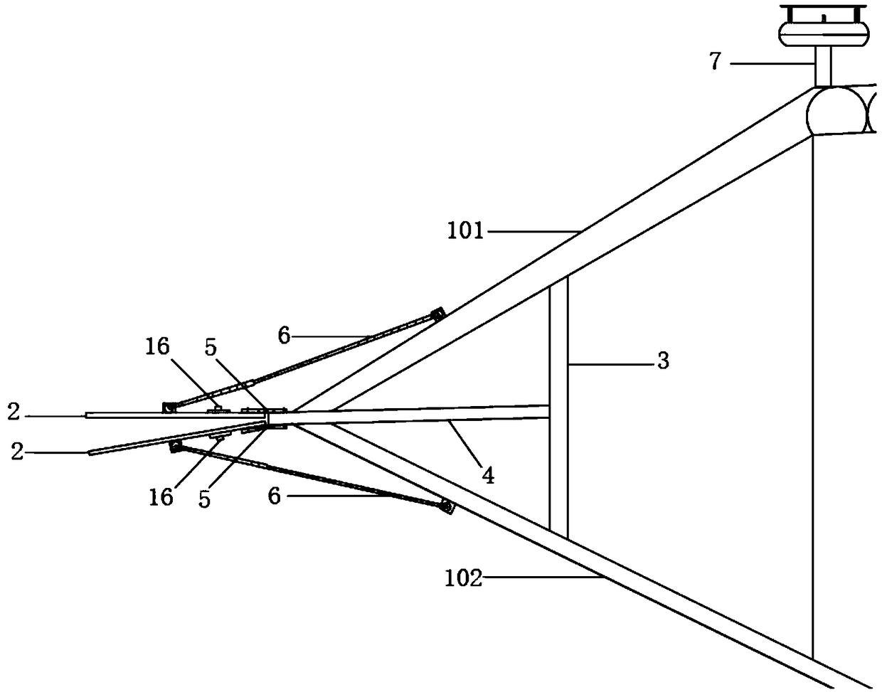
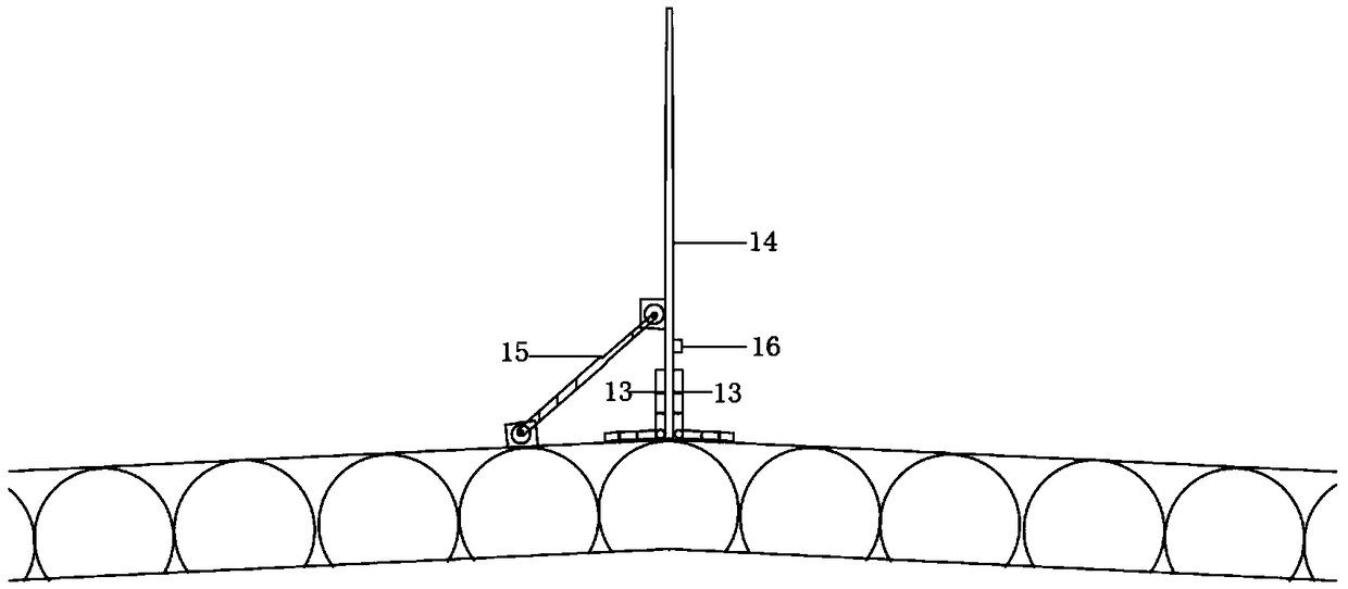
[0039] Wherein, the overall structural diagram of embodiment one is as follows Figure 1a As shown, the structure diagram of the adjustment mechanism is shown in Figure 1b shown;

[0040] Figure 1b The stroke environment detection processor 7 is installed on the bridge deck, and the central controller installed in it is embedded with an angle conversion program. The wind environment detection processor 7 measures the wind environment of the main girder in real time and transmits the signal to the central controller. The angle conversion program in the central controller can be programmed in advance so as to convert and output the movable deflector 2 and the movable center in real time. The angle that the stabilizing plate 14 needs to rotate under different wind environments and the length that the hydraulic numerical control telescoping rod needs to be extended or shortened, the central controller sends a signal to start the device in real time to ensure that the movable de...

Embodiment 2

[0045] The overall structure diagram of embodiment two is as follows Figure 2a As shown, the structure diagram of the adjustment mechanism is shown in Figure 2b shown;

[0046] The basic principle of the second embodiment is the same as that of the first embodiment, and the signal transmission and accessory cooperation paths are: wind environment detection processor 7 → hydraulic numerical control telescopic rod 6 → movable deflector 2 → angle sensor 16 → wind environment detection processor 7 Wind environment detection processor 7 → central hydraulic numerical control telescopic rod 15 → movable central stabilizing plate 14 → angle sensor 16 → wind environment detection processor 7, the specific connection and operation principle between each accessory are the same as embodiment one, no more details .

[0047] The adjustment mechanism includes a rotary bearing outer ring 8, a rotary bearing inner ring 9, and a rotary bearing shaft 10. The rotary bearing outer ring 8 is a ...

Embodiment 3

[0049] The overall structure diagram of embodiment three is as follows Figure 3a As shown, the detailed structure diagram of the rotatable deflector is shown in Figure 3b shown;

[0050] In addition to the movable deflector 2 and the movable central stabilizing plate 14, the accessories used in the third embodiment also adopt the wind environment detection processor 7, the hydraulic numerical control telescopic rod 6, and the angle sensor 16 used in the first and second embodiments. The connection, operation, and signal transmission path principles between the accessories are the same as those in the first and second implementations, and will not be repeated here.

[0051] The movable deflector 2 runs through the gap between the upper steel plate 101 of the fish mouth and the lower steel plate 102 of the fish mouth. 102 is provided with a hydraulic numerical control telescopic rod 6, the hydraulic numerical control telescopic rod 6 is respectively hinged with the movable d...


PUM


Abstract

The invention discloses an active control system and method for improving the large-span bridge wind-resistant performance. The active control system comprises a flow guide plate and a central stabilizer, both of which can rotate by corresponding angles according to changes of wind environments such as different wind attack angles. The active control system detects a wind environment signal through a wind environment detection processor, the signal is transmitted to a central control unit inside the system, the telescopic length of a hydraulic numerical control telescopic rod and the rotatingangles of the flow guide plate and the central stabilizer are obtained through conversion conducted by an angle conversion procedure embedded in the central control unit, a length signal is then transmitted to the hydraulic numerical control telescopic rod, and the telescopic rod stretches and retracts by the corresponding length to achieve the rotating angles of the flow guide plate and the central stabilizer. Compared with the prior art, the flow guide plate and the central stabilizer can be rotated to make gas be better divided and flow around a bridge structure, the wind-resistant performance of a bridge in different wind environments can be effectively improved, the wind-induced vibration amplitude of the bridge structure is reduced, the aerodynamic performance of the bridge is improved, and the traveling comfort of vehicles traveling on the bridge in windy weather is improved.

Description

technical field [0001] The invention relates to an active control system and a control method for improving the wind resistance performance of a long-span bridge, belonging to the technical field of civil engineering. Background technique [0002] With the increasing traffic demand of people, the bridge construction is developing in the direction of long-span and light weight, and at the same time, the problem of wind-induced vibration has become more and more prominent. The bridge has a large amplitude in a windy environment, which greatly reduces the comfort of driving vehicles, hinders or even interrupts transportation, and seriously affects the development of the transportation economic belt. Once a bridge is damaged by wind disasters, the consequences will be very serious. In addition, wind damage to bridges occurs more frequently than earthquake damage. The wind stability of long-span bridges has become one of the controlling factors that cannot be ignored in bridge de...

Claims


Application Information

Patent Timeline
IPC IPC(8): E01D19/00G05D3/12
CPCE01D19/00G05D3/12
Inventor 杨明田林杰万丽娟常山李喆陈章刘奎
Owner SOUTHEAST UNIV
Learn More