Puller type water draining gas recovering plunger

A kind of drainage gas production and pumping technology, which is used in the production of fluids, earthwork drilling and production, wellbore/well components, etc. Leakage and other problems, to achieve the effect of reducing the amount of leakage

Pending Publication Date: 2018-11-06
陕西圣润能源环保科技有限公司
View PDF8 Cites 6 Cited by
  • Summary
  • Abstract
  • Description
  • Claims
  • Application Information

AI Technical Summary

Problems solved by technology

[0003] At present, the commonly used plungers for drainage and gas production include solid plungers, brush plungers, liner plungers and quick plungers. The common disadvantage of them is that they cannot control the amount of liquid lifted in a single working cycle of the plunger and the lifting liquid. Serious omission
When there is too much liquid accumulation, the plunger tool cannot reach the wellhead smoothly, and the process fails; when the liquid accumulation is small, the formation pressure recovery time is short, the upward speed of the plunger is slow, the liquid leakage is serious during the lifting process, and the plunger discharges Liquid effect is poor

Method used


Image

  • Puller type water draining gas recovering plunger
  • Puller type water draining gas recovering plunger
  • Puller type water draining gas recovering plunger

Examples


Embodiment Construction

[0015] The present invention is described in detail below in conjunction with accompanying drawing.

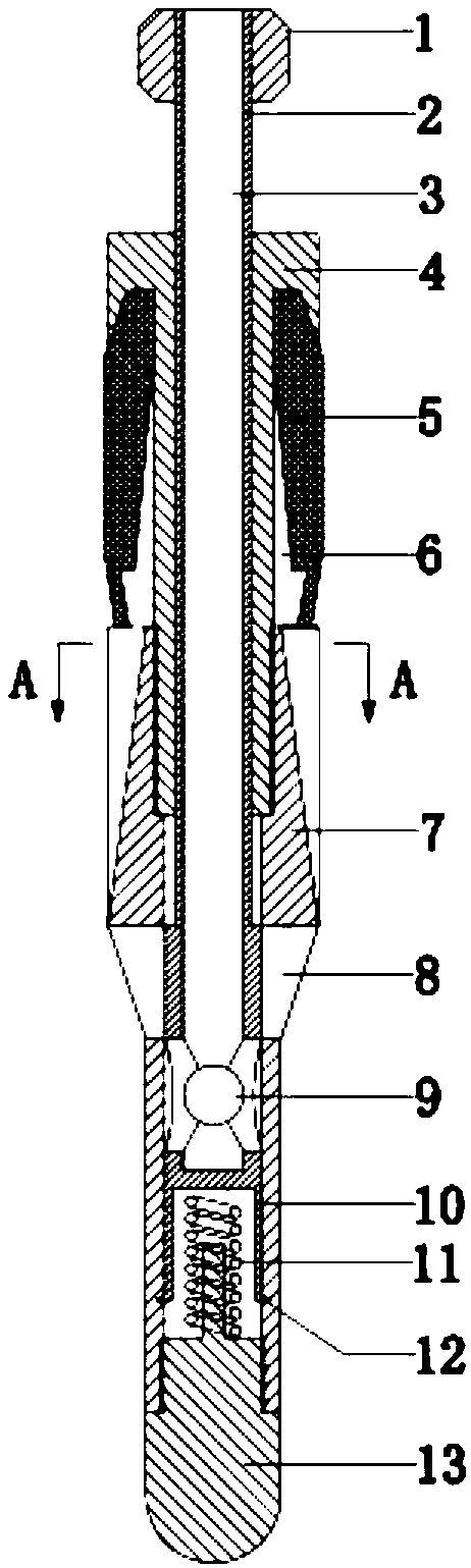
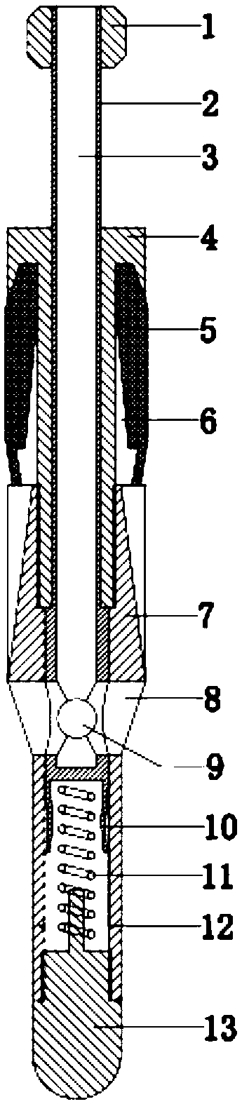
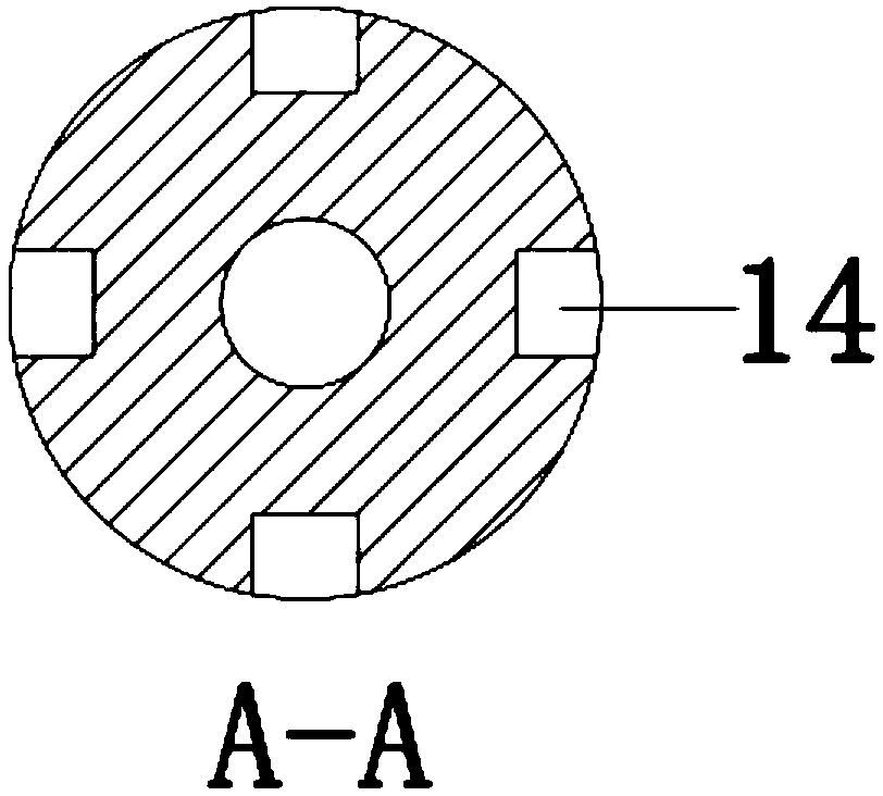
[0016] refer to figure 1 , a pumping type drainage and gas production plunger, including a plunger body 4 with a hollow structure, the inner cavity of the plunger body 4 is provided with a sliding sleeve 2 that slides up and down, the upper part of the sliding sleeve 2 is a hollow structure, and the inner channel 3 is circumferentially provided with Four evenly distributed sliding sleeve liquid inlet holes 9; the bottom of the sliding sleeve 2 is provided with claws 10; the top of the sliding sleeve 2 is connected to the fishing head 1 through threads;

[0017] A sealing rubber cylinder 5 is inserted into the groove of the plunger body 4, and the sealing rubber cylinder 5 is fixed by the lower half cylinder 7 of the plunger, and the lower half cylinder 7 of the plunger is connected with the plunger body 4 through threads; refer to image 3 The plunger lower half cylinder 7 is...


PUM


Abstract

The invention discloses a puller type water draining gas recovering plunger. A sliding sleeve is arranged in an inner cavity of a plunger body. The sliding sleeve is of a hollow structure, four uniformly distributed sliding sleeve liquid inlet holes are formed in the circumferential direction mode in a channel in the sliding sleeve. A clamping jaw is arranged at the bottom of the sliding sleeve. The top of the sliding sleeve is connected with a salvage head by threads. A lower half cylinder of the plunger is connected with the plunger body by threads, and four uniformly distributed air-in channels and plunger liquid inlet holes are correspondingly formed in the circumferential direction of the lower half cylinder of the plunger. The bottom of the lower half cylinder of the plunger is connected with a spring base by threads. The spring, with one end abuts against the sliding sleeve and the other end abuts against the spring base, is compressed in an inner cavity of the lower half cylinder of the plunger. During the down stroke of the plunger, accumulated liquid flows to the upper portion of the plunger through the channel in the sliding sleeve, quick descending of the plunger is achieved; upper portion liquid increases and pushes the sliding sleeve to move downwards corresponding to the lower half cylinder of the plunger to enable the clamping jaw to clamp to a clamping jaw positioning groove; and replacement of the spring achieves change of one-time period liquid lifting quantity. During the up stroke, gas at the bottom of the plunger acts on the inner walls of sealing rubber cylinders through gas inlet channels to expand the sealing rubber cylinders to be tightly attached to an oil pipe, and therefore full sealing of the plunger and the oil pipe is achieved.

Description

technical field [0001] The invention belongs to an underground drainage and gas production tool in the field of petroleum and natural gas exploitation, in particular to a pumping type drainage and gas production plunger. Background technique [0002] The plunger gas lift drainage gas recovery method is a widely used intermittent drainage gas recovery measure. The plunger gas lift method can reduce bottomhole fluid accumulation and prolong the production time of gas wells. At the same time, the plunger gas lift can also be used in oil and gas wells that are prone to wax and scale, eliminating the need for cleaning wax and scale. However, there are still some problems, such as discontinuous production, long shut-in time, and large fluid loss during ascent. [0003] At present, the commonly used plungers for drainage and gas production include solid plungers, brush plungers, liner plungers and quick plungers. The common disadvantage of them is that they cannot control the amo...

Claims


Application Information

Patent Timeline
Patent Type & Authority Applications(China)
IPC IPC(8): E21B43/00
CPCE21B43/122E21B43/123
Inventor 徐建宁王熙柳愿席鹏超王毅博黄泽奇
Owner 陕西圣润能源环保科技有限公司
Why Eureka
Try Eureka