Annular gap and disc-shaped gap combined large adjustable damping range magneto-rheological damper

A magnetorheological shock absorber and annular gap technology, which is applied in the field of vehicle engineering, can solve the problems of the magnetorheological shock absorber, such as small variable damping force range, poor applicability, and inability to adjust, to achieve fast response time and large damping The effect of high adjustment range and system linearity

Inactive Publication Date: 2018-11-06
TSINGHUA UNIV
View PDF5 Cites 12 Cited by
  • Summary
  • Abstract
  • Description
  • Claims
  • Application Information

AI Technical Summary

Problems solved by technology

[0002] The vehicle is a complex system composed of many subsystems. During the driving process of the vehicle, the vibration generated by the unevenness of the ground or the operation of the power system is transmitted through each subsystem. The damping system between the subsystems of the related technology uses a fixed damping coefficient. Therefore, the ideal required damping force cannot be generated in the wide frequency domain, and it cannot be adjusted according to specific needs, and the applicability is poor. At the same time, the range of variable damping force of the magneto-rheological shock absorber is small, which needs to be solved

Method used


Image

  • Annular gap and disc-shaped gap combined large adjustable damping range magneto-rheological damper
  • Annular gap and disc-shaped gap combined large adjustable damping range magneto-rheological damper

Examples


Embodiment Construction

[0020] Embodiments of the present invention are described in detail below, examples of which are shown in the drawings, wherein the same or similar reference numerals designate the same or similar elements or elements having the same or similar functions throughout. The embodiments described below by referring to the figures are exemplary and are intended to explain the present invention and should not be construed as limiting the present invention.

[0021] A magneto-rheological shock absorber with a large adjustable damping range combined with an annular gap and a disc-shaped gap proposed according to an embodiment of the present invention will be described below with reference to the accompanying drawings.

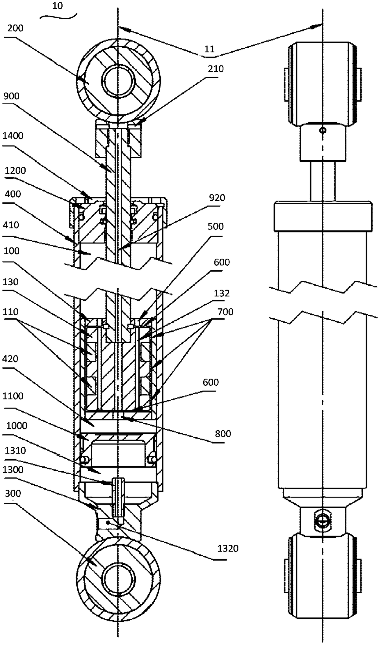
[0022] figure 1 It is a structural schematic diagram of a magneto-rheological shock absorber with a large adjustable damping range combined with an annular gap and a disc-shaped gap according to an embodiment of the present invention.

[0023] like figure 1 As shown, ...


PUM


Abstract

The invention discloses an annular gap and disc-shaped gap combined large adjustable damping range magneto-rheological damper. The annular gap and disc-shaped gap combined large adjustable damping range magneto-rheological damper comprises a piston, an upper connecting ring, a lower connecting ring and a work cylinder. The piston comprises a magnet exciting coil. The upper connecting ring and thelower connecting ring are connected with a first body and a second body of a vehicle correspondingly, and accordingly the axis of the damper is located in the opposite movement direction of the firstbody and the second body. The piston divides the work cavity into an upper cavity and a lower cavity. The work cylinder contains magneto-rheological liquid, and accordingly when the first body and thesecond body oppositely move in the axis direction of the damper, the magneto-rheological liquid flows between the work cylinder upper cavity and the work cylinder lower cavity through the piston, thefluid characteristic of the magneto-rheological liquid can be controllably changed under the action of a changeable magnetic field generated due to electrification of the coil, accordingly the damping force of the damper is changed, and then vibration transmission between the first body and the second body is absorbed. According to the damper, the damper large damping range controllable adjustment can be achieved under the situation that the magneto-rheological liquid rheological property is not efficient enough, the response time is short, and system linearity is high.

Description

technical field [0001] The invention relates to the technical field of vehicle engineering, in particular to a magneto-rheological shock absorber with a large adjustable damping range combined with an annular gap and a disc-shaped gap. Background technique [0002] The vehicle is a complex system composed of many subsystems. During the driving process of the vehicle, the vibration generated by the unevenness of the ground or the operation of the power system is transmitted through each subsystem. The damping system between the subsystems of the related technology uses a fixed damping coefficient. Therefore, the ideal required damping force cannot be generated in a wide frequency domain, and it cannot be adjusted according to specific needs, and the applicability is poor. At the same time, the range of variable damping force of the magneto-rheological shock absorber is small, which needs to be solved. Contents of the invention [0003] The present invention aims to solve on...

Claims


Application Information

Patent Timeline
Patent Type & Authority Applications(China)
IPC IPC(8): F16F9/53F16F9/34F16F9/06
CPCF16F9/067F16F9/3405F16F9/535F16F9/537
Inventor 危银涛陈亚龙冯占宗韩晓东张焕何一超康振冉梁冠群李雪冰彭靖邬明宇
Owner TSINGHUA UNIV
Why Eureka
Try Eureka