A simulation test bench for shield machine cutter head and its use method

A technology for simulating test benches and shield machines, which is applied in the testing of mechanical components, testing of machine/structural components, earthwork drilling and mining, etc., to achieve the effect of meeting strength requirements, reducing risks and costs, and being easy to process

Inactive Publication Date: 2019-11-05
NORTHEASTERN UNIV LIAONING
View PDF6 Cites 0 Cited by
  • Summary
  • Abstract
  • Description
  • Claims
  • Application Information

AI Technical Summary

Problems solved by technology

[0006] Aiming at the shortcomings in the prior art that there is no simulation test bench that can cooperate with the hob tool change robot to simulate tool change, the problem to be solved by the present invention is to provide a simulation test bench for the shield machine cutter head and its use method, using A tool change that simulates actual working conditions with an auxiliary disc hob tool change robot

Method used


Image

  • A simulation test bench for shield machine cutter head and its use method
  • A simulation test bench for shield machine cutter head and its use method
  • A simulation test bench for shield machine cutter head and its use method

Examples


Embodiment Construction

[0031] The present invention will be further elaborated below in conjunction with the accompanying drawings of the description.

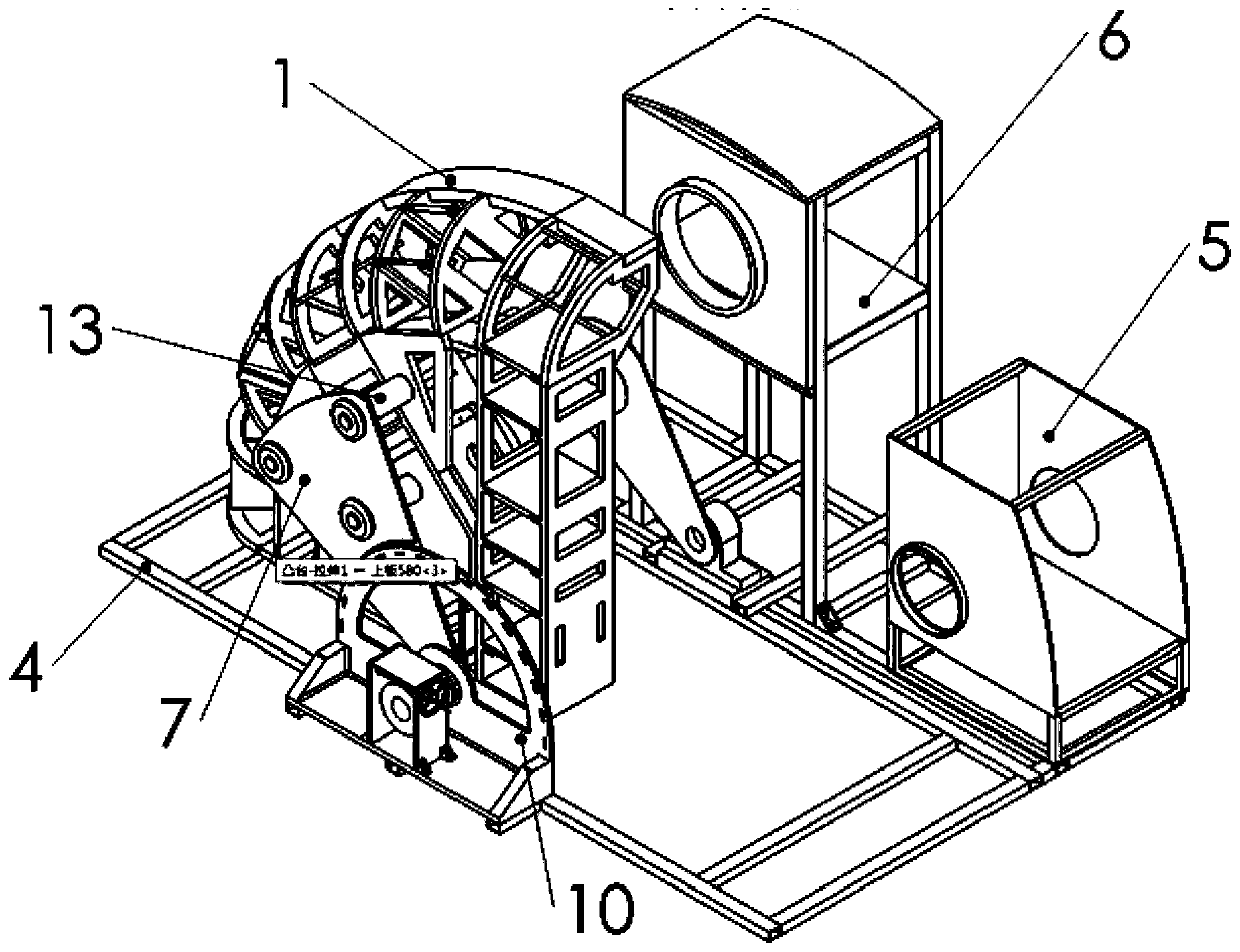
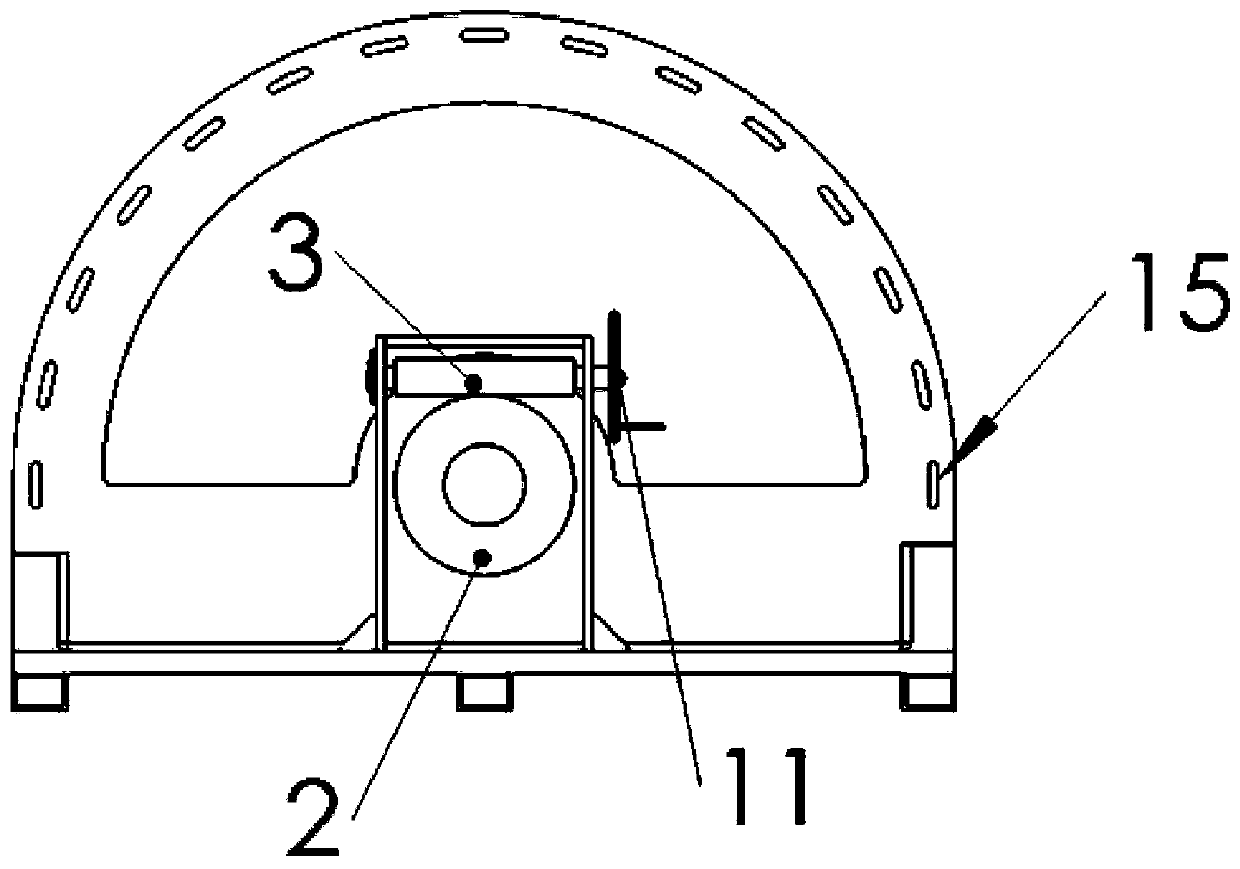
[0032] Such as Figure 1~4 As shown, a simulation test bench of a shield machine cutter head in the present invention includes: a cutter head 1, a worm gear structure, a base 4, a knife storage bin 5, and a manipulator installation bin 6, wherein the cutter head 1 is installed by rotating the mounting plate On the base, the knife storage bin 5 and the manipulator installation bin 6 are all installed on the base 4, and the worm gear structure is installed on the side of the base 4 and the side of the cutter head 1. In the worm gear structure, the shaft of the worm wheel 2 and the cutter head 1 The shafts are coaxially fixed together, and the worm gear structure is provided with a hand wheel 11, and the hand wheel 11 is axially fixedly connected with the worm 3 in the worm gear structure.

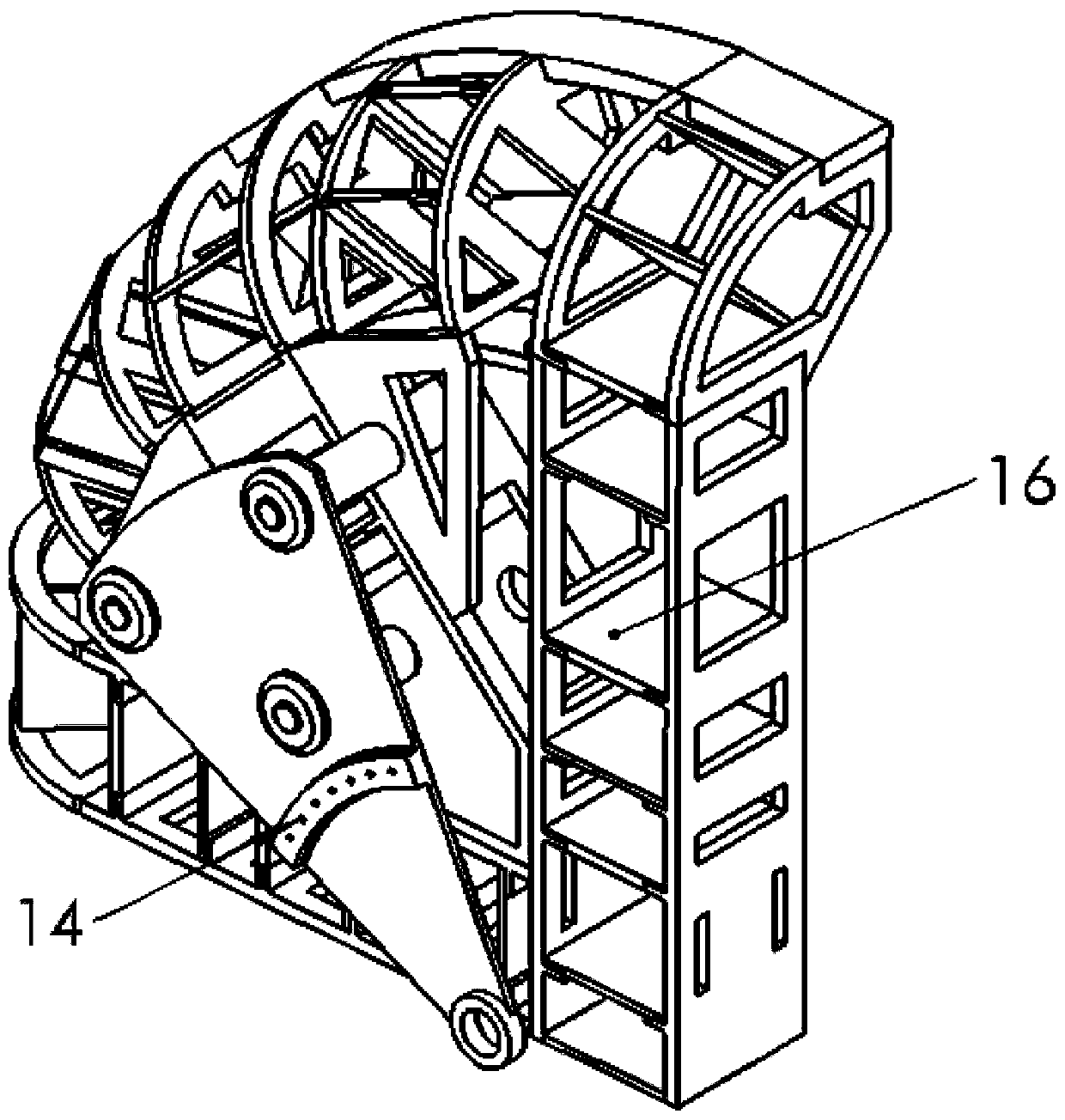
[0033] Such as figure 2 As shown, the cutter head is a qua...


PUM


Abstract

The invention relates to a simulation test bench for the cutter head of a shield tunneling machine and a use method of the simulation test bench. The simulation test bench comprises a cutter head, a worm wheel / worm structure, a base, a storage cutter bin and a mechanical arm mounting bin; the cutter head is rotatably mounted on the base through a mounting plate; the storage cutter bin and the mechanical arm mounting bin are both mounted on the base; the worm wheel / worm structure is mounted on one edge of the base and is located at one side of the 1 / 4 of the surface of the cutter head; a worm wheel shaft in the worm wheel / worm structure is coaxially and fixedly connected with the shaft of the mounting plate; the worm wheel / worm structure is provided with a hand wheel; and the hand wheel isfixedly and axially connected with a worm shaft in the worm wheel / worm structure. The test method includes the following steps that: a hobbing cutter box is fixed; a cutter head is rotated; the cutterhead is fixed; a cutter change robot is installed; and cutter change is simulated, position information is inputted to the cutter change robot, and the trajectory planning and motion accuracy of thecutter change robot are verified. According to the simulation test bench of the invention, the worm wheel / worm integrated structure is adopted, so that separate small parts are avoided, and therefore,the simulation test bench has the advantages of convenience in installation and operation, structural simplicity and easiness in processing, and meets a strength requirement and conforms to actual engineering application.

Description

technical field [0001] The invention relates to a construction machinery test device, in particular to a simulation test bench for a shield machine cutterhead and a method for using the same. Background technique [0002] At present, there are two ways to change the tool of the slurry balance shield machine, normal pressure tool change and pressure tool change. , the conditions for manual tool change under pressure are harsh. Operators enter the mud tank under pressure to inspect and replace worn hobs. They need to withstand high pressure and high humidity, and are prone to accidents and life-threatening. In the case of immature technology of tool changing robots, it is not convenient to carry out tool changing experiments in actual working environments. [0003] The disc-shaped hob of the slurry balance shield machine needs to be replaced many times during the entire project period, and each time the hob is replaced, the angular position of the hob that needs to be replac...

Claims


Application Information

Patent Timeline
Patent Type & Authority Patents(China)
IPC IPC(8): G01M13/00E21D9/08
CPCE21D9/08G01M13/00
Inventor 王亚文徐晨李海洋谢里阳杜东旭赵东磊
Owner NORTHEASTERN UNIV LIAONING
Why Eureka
Try Eureka