Diagnostic method of aero-engine rotor fault

An aero-engine and diagnostic method technology, which is applied in the testing of engines, testing of machine/structural components, measuring devices, etc., can solve the problem of single diagnostic method, reasonable extraction of rotor fault features, and inability to effectively filter noise background spectrum. To achieve the effect of easier determination of clustering parameters, removal of noise interference, and convenient selection

Active Publication Date: 2018-11-06
NANCHANG HANGKONG UNIVERSITY
View PDF4 Cites 19 Cited by
  • Summary
  • Abstract
  • Description
  • Claims
  • Application Information

AI Technical Summary

Problems solved by technology

[0005] These methods have made some contributions to the fault diagnosis and signal feature extraction of the aero-engine rotor system. The operating state of the system is not comprehensive enough
[0006] At the same time, the patent with the authorized announcement number of CN101968379B and the patent application with the application publication number of CN107506709A respectively disclose two methods for extracting characteristic information of the fault signal of the rotor system of the aeroengine. Both methods use the eddy current displacement sensor to measure the vibration signal , and use wavelet clustering with different ideas to analyze, mine hidden feature information from a large number of vibration displacement signals, and realize the extraction of working condition features. The former method still has certain deficiencies in the extraction accuracy and speed, and the latter An extraction method has made a breakthrough improvement on the basis of the former, but it still has a common problem with the former, that is, the noise background spectrum cannot be effectively filtered out in the extraction results, and the weak fault feature information and The frequency spectrum impact amplitude of fault feature information is close, which affects the reasonable extraction of rotor fault features to a certain extent. make further improvements

Method used


Image

  • Diagnostic method of aero-engine rotor fault
  • Diagnostic method of aero-engine rotor fault
  • Diagnostic method of aero-engine rotor fault

Examples


Embodiment example

[0066] An implementation case of a diagnosis method for an aeroengine rotor fault, including the following process:

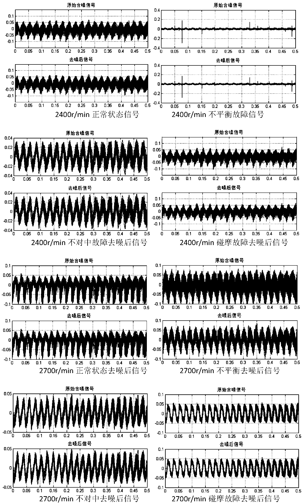
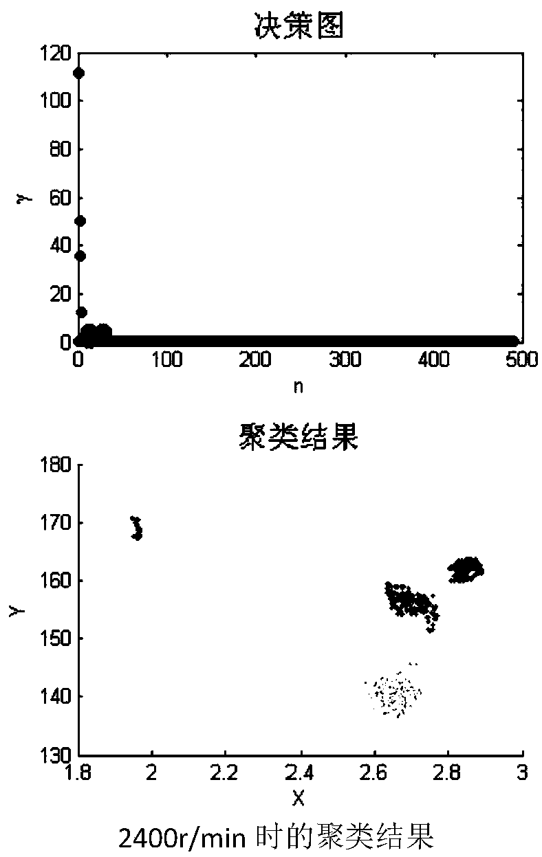
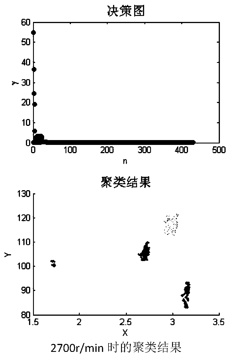
[0067] The first step is to collect the vibration acceleration signal of the aeroengine rotor; through the eddy current acceleration sensor, select the data of the aeroengine rotor speed of 2400r / min and 2700r / min, the sampling frequency is 10240HZ, the sample length is 8192, and the number of samples is 1525 groups; implement In the case, the signal collected by the acceleration sensor in the horizontal direction of the left casing is selected. The signal is a discrete vibration acceleration signal. Since there may be errors at the beginning and end of each group of signals, in signal processing and calculation, only each group is used. The 5120 data in the middle section of the group data, and finally mainly adopt the relatively stable state of the comprehensive state of the rotor, and analyze the data. There are 151 groups of data in the normal state, 100 gro...


PUM


Abstract

The invention discloses a diagnostic method of an aero-engine rotor fault. According to the method, an eddy current acceleration sensor is firstly utilized to collect a vibration acceleration signal of an aero-engine rotor, then noise reduction processing is performed on the vibration acceleration signal of the aero-engine rotor, and the signal characteristic quantity of the aero-engine rotor after the noise reduction is extracted, and then clustering analysis is performed on the signal characteristic quantity based on automatic density peak clustering of Mahalanobis distance. According to thefault diagnosis method, wavelet decomposition is utilized, threshold processing is performed, and then noise interference is removed from a signal by lifting wavelet reconstruction; the signal characteristic quantity after the noise reduction is extracted, and the clustering analysis is performed on the signal characteristic quantity based on the automatic density peak clustering of Mahalanobis distance, so that the noise interference can be eliminated to a minimum value, the diagnosis of fault information of the aero-engine rotor can be realized, and fault results of various aero-engine rotors can be quickly obtained.

Description

technical field [0001] The invention relates to a method for diagnosing a mechanical failure, in particular to a method for diagnosing a rotor failure of an aeroengine. Background technique [0002] The aircraft engine is the heart of the aircraft. It is the system with the highest failure rate, the most complicated adjustment and the largest maintenance workload in the aviation machinery equipment. The quality of its working status directly affects the safety, reliability and operation of the aircraft. Once the engine fails during operation, it may cause the aircraft to fail to fly normally, endanger personal safety, and cause significant social and economic losses. [0003] According to statistics, the failure rate of aero-engines accounts for about 30% of all aircraft failures, and about 40% of major flight accidents due to mechanical reasons are caused by engine failures. Engines are different from general machinery due to their own characteristics, even if they are very...

Claims


Application Information

Patent Timeline
Patent Type & Authority Applications(China)
IPC IPC(8): G01M15/02
CPCG01M15/02
Inventor 刘晓波辜振谱熊震
Owner NANCHANG HANGKONG UNIVERSITY
Why Eureka
Try Eureka