
Motor controller

A control device and motor technology, applied in motor control, non-electric variable control, computer control, etc., can solve the problems of notch filter's step response overshoot and unsatisfactory processing quality, etc.

Inactive Publication Date: 2017-10-03
FANUC LTD
View PDF2 Cites 2 Cited by
  • Summary
  • Abstract
  • Description
  • Claims
  • Application Information

AI Technical Summary

Problems solved by technology

The reason is that the step response of the notch filter produces overshoot, which is easy to understand
If the command path overshoots due to the use of the notch filter, marks corresponding to the overshoot will be left on the workpiece, and the processing quality will not be as ideal.

Method used


Image

  • Motor controller
  • Motor controller
  • Motor controller

Examples


Embodiment Construction

[0015] Next, a motor control device according to the present invention will be described with reference to the drawings.

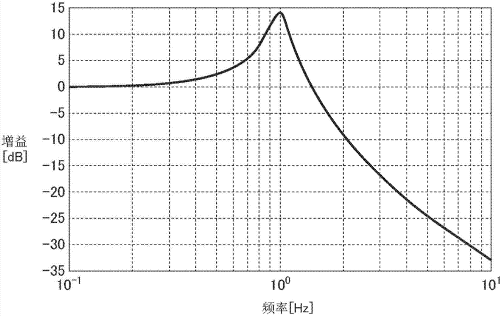
[0016] First, an invention related to the present invention and an invention related to a related application filed by the applicant (Japanese Patent Application No. 2015-007219) will be described. exist figure 1 , a block diagram of a motor control device according to an invention related to the present invention is shown. The motor control device according to this related invention is a motor control device that corrects a position command using an inverse characteristic filter F(s) from a motor position to a machine position.

[0017] figure 1 The motor control device 1000 shown has a position instruction unit 1001, a correction filter unit 1002, a servo control unit 1003, an element 1004 representing a transfer characteristic from torque to a machine position, and an element representing a transfer characteristic from torque to a motor position 1005...


PUM


Abstract

The invention discloses a motor controller. The motor controller according to the present invention includes a position command unit for commanding the position of a driven unit, a compensation filter unit for compensating a position command, and a servo control unit for controlling the operation of a servomotor based on a compensated position command. The compensation filter unit includes an inverse characteristic filter for approximating an inverse characteristic of a transfer characteristic from a motor position to a mechanical position, and a high frequency cutoff filter for reducing a high frequency component of the position command. The inverse characteristic filter is a filter for reducing a gain at a mechanical resonance frequency [omega]0. The high frequency cutoff filter has a constant ''a'' times high frequency cutoff frequency a [omega]0 using a constant ''a'' of 1 or more, with respect to the mechanical resonance frequency a[omega]0 determined in the inverse characteristic filter.

Description

technical field [0001] The present invention relates to a motor control device, in particular to a motor control device with a function of suppressing vibration. Background technique [0002] Conventionally, in a motor control device that drives a machine with a motor, the servo control system has a low-pass filter or a notch filter to deal with high-frequency resonance. These filters exist in the control loop of the servo, and their purpose is not to correct the position command, but to improve the responsiveness and stability of the servo. [0003] On the other hand, in the past, the following methods have been adopted for low-frequency resonance: using smooth commands (for example, Japanese Patent Application Laid-Open No. 2009-237916), implementing notch filtering for commands, and using input shaping for commands (for example, "PreshapingCommand Inputs to Reduce System Vibration", MASSACHUSETTS INSTITUTE OFTECHNOLOGY ARTIFICIAL INTELLIGENCE LABORATORY, A.I. Memo No. 10...

Claims


Application Information

Patent Timeline
Patent Type & Authority Applications(China)
IPC IPC(8): H02P29/00G05D19/02G05B19/404
CPCG05B19/404G05D19/02H02P29/00G05B2219/41121G05B2219/41144G05B2219/41187G05B2219/41222G05B2219/41232G05B19/048G05B2219/39199
Inventor 中邨勉猪饲聪史
Owner FANUC LTD
Learn More