
Wavelength division multiplexing based integrated multi-beam optical phased array delay network

A technology of delay network and optical phased array, which is applied in the field of optical phased array, can solve the problems of poor stability and huge system, achieve the effect of small size, full utilization, and improvement of instantaneous bandwidth and resolution

Active Publication Date: 2018-11-06
SHANGHAI JIAO TONG UNIV
View PDF8 Cites 23 Cited by
  • Summary
  • Abstract
  • Description
  • Claims
  • Application Information

AI Technical Summary

Problems solved by technology

However, these are all composed of discrete devices, which will bring problems such as large system size and poor stability, and most of them are only single beamforming networks

Method used


Image

  • Wavelength division multiplexing based integrated multi-beam optical phased array delay network
  • Wavelength division multiplexing based integrated multi-beam optical phased array delay network
  • Wavelength division multiplexing based integrated multi-beam optical phased array delay network

Examples


Embodiment Construction

[0027] The embodiments of the present invention will be described in detail below in conjunction with the accompanying drawings and Examples. This embodiment is implemented on the premise of the technical solution of the present invention, and detailed implementation methods and operating procedures are provided, but the protection scope of the present invention is not limited to Examples described below.

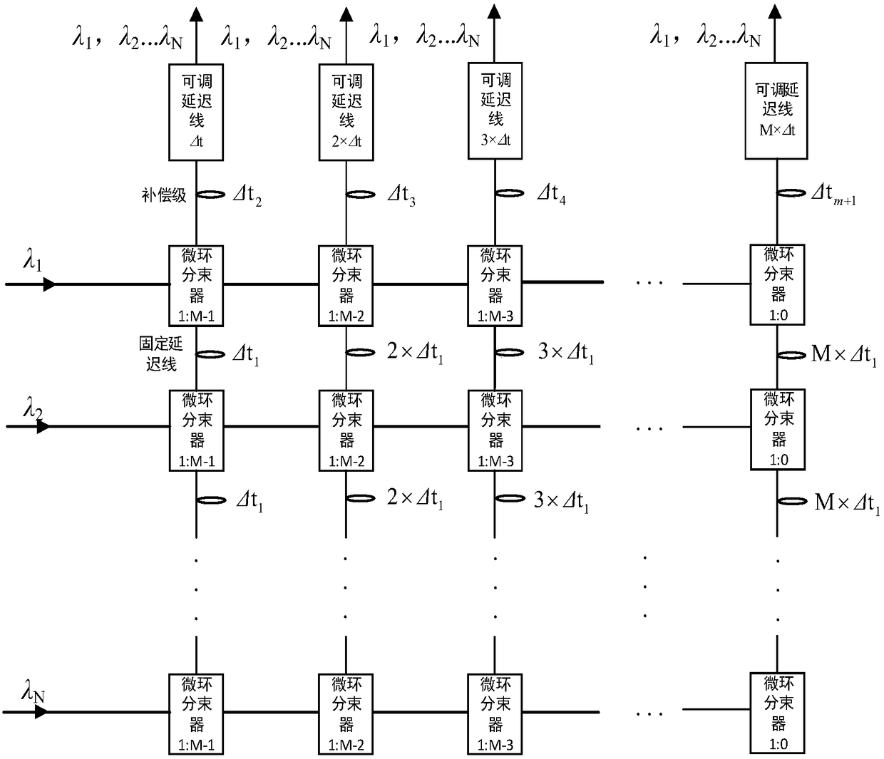
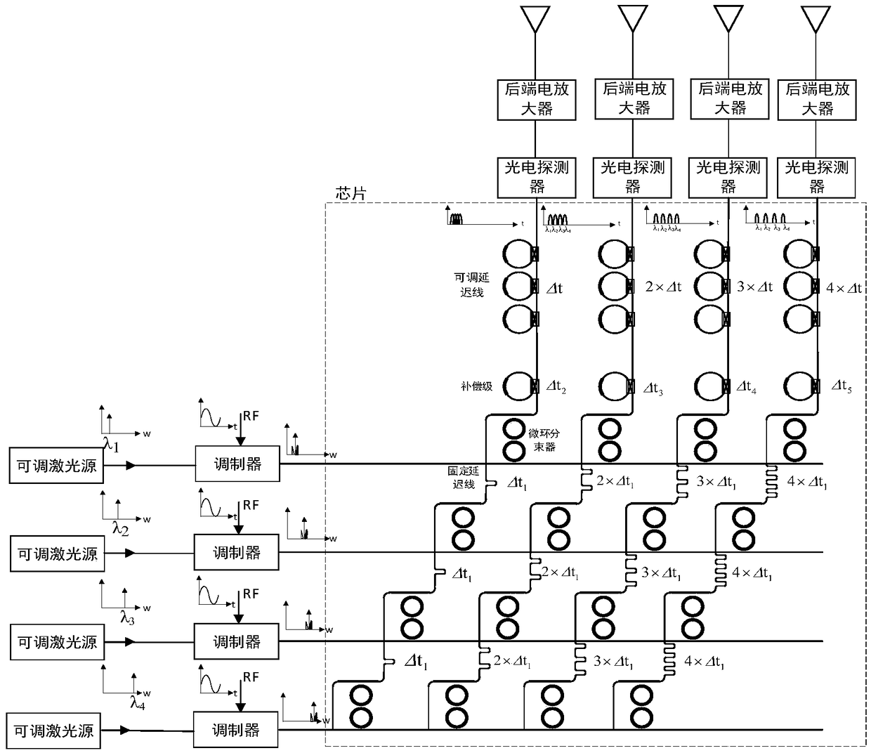
[0028] figure 1 It is a schematic diagram of the overall architecture structure of the integrated multi-beam optical phased array delay network based on wavelength division multiplexing of the present invention. It can be seen from the figure that an integrated multi-beam optical phased array delay network based on wavelength division multiplexing of the present invention has its characteristics In that, it is composed of N traveling waveguides, N×M microring beam splitters, N×M fixed optical true delay networks, M adjustable optical true delay arrays and M column waveguide...


PUM


Abstract

A wavelength division multiplexing based integrated multi-beam optical phased array delay network for a microwave photonic multi-beam phased array radar, consists of N-channel row waveguides, NxM micro-ring beam splitters, an NxM fixed photo-true delay network, M-channel dimmable true delay arrays and M-channel column waveguides; the NxM micro-ring beam splitters are arranged in N rows and M columns; and the NxM fixed photo-true delay network is connected to the NxM micro-ring beam splitters. The invention only needs M adjustable units, and can realize the phased array radar of M array elements and N beams, is simple and flexible in structure control, is high in integration degree, and is large in instantaneous bandwidth and high in resolution.

Description

technical field [0001] The invention relates to an optical phased array, in particular to an integrated multi-beam optical phased array delay network based on wavelength division multiplexing. Background technique [0002] Radar is the transliteration of Radar (Radio Detection and Ranging). It first appeared in the 1930s. Its basic working principle is to receive the transmitted signal through the receiver and perform a series of calculations to obtain the distance of the detection target. , angle information, etc. When the radar searches for the target, it needs to constantly change the direction of the beam. The traditional method of changing the beam direction is to rotate the antenna so that the beam sweeps across a certain airspace, ground or sea surface, which is called mechanical scanning. The radar that uses mechanical scanning is conventional radar. Due to the inertia of the antenna, the scanning speed is slow, the accuracy is low, and the reliability is not high....

Claims


Application Information

Patent Timeline
Patent Type & Authority Applications(China)
IPC IPC(8): G01S13/02
CPCG01S13/02G01S2013/0245Y02A90/10
Inventor 陆梁军朱晨周林杰陈建平刘娇
Owner SHANGHAI JIAO TONG UNIV
Learn More