
Powder cleaning device of remanufactured toner cartridge

A technology for cleaning powder and toner cartridges, which is applied in the fields of electrical recording, optics, instruments, etc., can solve problems such as affecting the health of operators, high labor intensity, and affecting printing quality.

Inactive Publication Date: 2018-11-06
王卫华
View PDF0 Cites 1 Cited by
  • Summary
  • Abstract
  • Description
  • Claims
  • Application Information

AI Technical Summary

Problems solved by technology

[0003] In the production process of regenerated toner cartridges, there is a process to clean the toner between the surface of the powder knife and the developing roller and the toner between the powder knife and the developing roller, so as to avoid the mutual extrusion of the powder knife and the developing roller during the transportation process. Pressure produces defects that affect print quality
The traditional cleaning method is that the operator twists the driving gear with one hand to drive the developing roller to rotate, and the other hand uses an air gun or brush to clean the work. The labor intensity is high and the cleaning efficiency is low. During the cleaning process, the toner particle size is small, It is easy to be inhaled into the body and seriously affect the health of operators

Method used


Image

  • Powder cleaning device of remanufactured toner cartridge
  • Powder cleaning device of remanufactured toner cartridge
  • Powder cleaning device of remanufactured toner cartridge

Examples


Embodiment 1

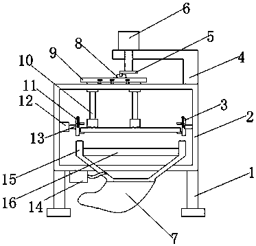
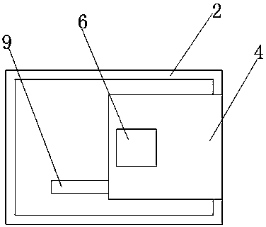
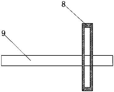
[0019] Example 1, in order to achieve the purpose of cleaning the toner cartridge, the toner cartridge is placed on the side of the first fixing plate 3, one end of the screw 11 extends into the through hole at the top of the first fixing plate 3, and the screw 11 is movably clamped in the through hole , the screw 11 can only rotate by itself and cannot move up and down. When the screw 11 is rotated, the screw 11 and the pressure plate 13 mesh with each other, and the screw 11 drives the pressure plate 13 to move downward. At the current position, connect the power supply to start the second motor 12, the second motor 12 drives the first fixed plate 3 to rotate, the first fixed plate 3 drives the toner cartridge to rotate, then connect the power again, start the first motor 6, and the first motor 6 drives the rotating disk 5 rotates, because one end of the matching rod on one side of the rotating disk 5 extends to the inside of the limit bar 8, the matching rod on the rotating ...

Embodiment 2

[0020] Embodiment 2, in order to achieve the purpose of collecting the powder, connect the power supply, turn on the suction pump 14, the strong suction of the suction pump 14 makes the powder flow through the filter screen 16, and flow into the collection bag 7. The cross section of the second support 15 is an isosceles trapezoid.


PUM


Abstract

The invention discloses a powder cleaning device of remanufactured toner cartridge. The powder cleaning device comprises a first bracket, a shell is welded at the top of the first bracket, one side ofinner wall of the shell is fixedly connected with a second motor through a bolt, and one end of the second motor is connected with a first fixed block through a key; a vertical section of the first fixed block is square, and a through hole is formed at the center shaft of the top of the first fixed block, a screw is movably clamped in the through hole; the through hole is formed on the sidewall of the first fixed block, a pressing plate is movably clamped in the through hole; one end of the pressing plate penetrates the through hole, and one end of the pressing plate extends into the first fixed block, and one end of the screw penetrates one end of the pressing plate. Through the device disclosed by the invention, the efficiency of cleaning the surface toner on the toner cartridge can beimproved, and the manpower cost can be saved, the work schedule is guaranteed, the physical labor of the cleaner is reduced, and the residual powder can be collected, the waste can be turned into wealth, and the powder cannot diffuse in the air, thereby reducing the influence degree on the cleaner body by the toner.

Description

technical field [0001] The invention relates to the technical field of printer equipment, in particular to a powder cleaning device for a regenerated toner cartridge. Background technique [0002] The basic structure of the toner cartridge is generally composed of a basic base material made of aluminum and a photosensitive material coated on the base material. According to different photosensitive materials, it can be basically divided into three types: OPC drum (organic photoconductive material), toner drum (Se selenium) and ceramic drum (a-si ceramic). In terms of lifespan, OPC drums have a short lifespan, generally only about 3,000 pages, and of course the price is the cheapest. The life of the Se drum is about 9000 pages, and the life of the a-si drum can reach 90,000 pages. The price naturally rises by analogy. In terms of composition, the general OPC drum has only three layers. The first layer is an aluminum tube, the second layer is an insulating layer, and the thi...

Claims


Application Information

Patent Timeline
IPC IPC(8): G03G21/00G03G21/12
CPCG03G21/0035G03G21/12
Inventor 不公告发明人
Owner 王卫华
Learn More