
Active vibration isolation controller and design method thereof

A technology of active vibration isolation and design method, applied in mechanical oscillation control, non-electric variable control, control/regulation system, etc., can solve the limit of active vibration isolation starting frequency, affect active vibration isolation performance, and feedforward bandwidth lower limit frequency Excessive expansion and other problems, to achieve the effect of improving low-frequency vibration isolation performance, avoiding control performance loss, and good low-frequency vibration isolation performance

Active Publication Date: 2018-11-06
HUAZHONG UNIV OF SCI & TECH
View PDF4 Cites 20 Cited by
  • Summary
  • Abstract
  • Description
  • Claims
  • Application Information

AI Technical Summary

Problems solved by technology

[0005] However, the geophone sensor has a second-order high-pass characteristic in the frequency domain. The amplitude of the input signal lower than the natural frequency of the geophone sensor itself will be significantly attenuated, and the phase will be advanced, resulting in distortion of the sensing signal in this frequency band. The starting frequency poses a great limitation
In practical applications, people often use bandwidth spread spectrum technology to improve the low-frequency measurement capability of the geophone sensor by compensating the low-frequency dynamic characteristics of the geophone sensor, but this method cannot improve the signal-to-noise ratio of the geophone sensor
However, people often determine the lower limit frequency of feedback control and feedforward control according to the signal-to-noise ratio of the ground tone sensor, which leads to the problem of insufficient expansion of the feedback bandwidth or excessive expansion of the lower limit frequency of the feedforward bandwidth, resulting in the instability of active vibration isolation control. , affecting the active vibration isolation performance

Method used

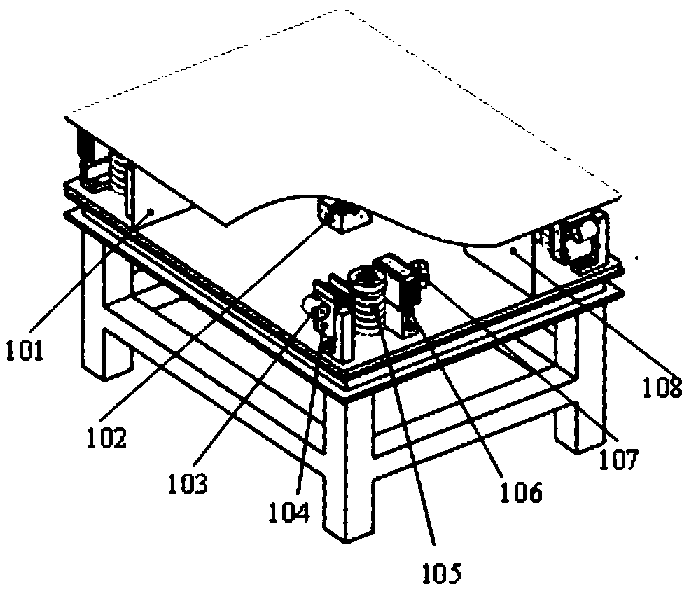
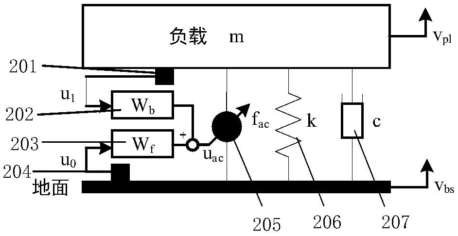

Image

  • Active vibration isolation controller and design method thereof
  • Active vibration isolation controller and design method thereof
  • Active vibration isolation controller and design method thereof

Examples


Embodiment Construction

[0052] In order to make the object, technical solution and advantages of the present invention clearer, the present invention will be further described in detail below in conjunction with the accompanying drawings and embodiments. It should be understood that the specific embodiments described here are only used to explain the present invention, not to limit the present invention. In addition, the technical features involved in the various embodiments of the present invention described below can be combined with each other as long as they do not constitute a conflict with each other.

[0053] see figure 1 , the design method of the active vibration isolation controller provided by the present invention, the design method considers the noise characteristics of the geophone sensor, and unifies the low frequency extension of the sensor with the active vibration isolation controller. The design method also comprehensively considers the impact of sensor low-frequency noise and dyn...


PUM


Abstract

The invention belongs to the field of technologies related with ultra-precision active vibration isolation, and discloses an active vibration isolation controller and a design method thereof. The design method comprises the following steps: (1) designing a feedback controller based on an equivalent model after acoustic emission sensor is extended to determine a bandwidth extension frequency pointof a feedback control error sensor; (2) designing the feedforward controller, and determining a bandwidth extension frequency point of a feedforward reference sensor according to a noise constraint condition, noise performance constraint condition being that the rVPSD of a load caused by noise in a feedback strategy is smaller than or equal to 0.707 times of the rVPSD of the load without the feedback strategy, and the noise constraint condition being that the noise equivalence speed of the feedforward reference sensor noise is smaller than or equal to 0.707 times of the rVPSD of foundation vibration. As low-frequency extension of the sensor and an active vibration isolation controller are unified, the stability is improved, and the control loss caused by insufficient or excessive bandwidthextension of the sensor is avoided.

Description

technical field [0001] The invention belongs to the technical field related to ultra-precision active vibration isolation, and more specifically relates to an active vibration isolation controller and a design method thereof. Background technique [0002] Vibration isolation technology is a basic technology for ultra-precision machining, manufacturing and measurement equipment, and electron microscopic imaging. It provides an ultra-quiet environment for the equipment and is the basic guarantee for the service performance of the equipment. As the precision of ultra-precision processing, manufacturing and measurement equipment evolves towards nanometers or even sub-nanometers, the equipment structure requires ultra-stable, and the strictness of the micro-vibration suppression frequency range and vibration isolation performance increases geometrically. The system is facing new challenges of near-zero low frequency, wide frequency domain, and ultra-micro-amplitude vibration iso...

Claims


Application Information

Patent Timeline
Patent Type & Authority Applications(China)
IPC IPC(8): G05D19/02
CPCG05D19/02
Inventor 罗欣丁基恒陈学东李小清刘军军姜伟曾理湛
Owner HUAZHONG UNIV OF SCI & TECH
Learn More