Pile mounting bracket and fuel cell using same

A technology for mounting brackets and fuel cells, which is applied to fuel cells, circuits, electrical components, etc., can solve the problems of complex structure, unreasonable structure settings, and single function of stack mounting brackets, and achieves easy handling and installation, simple structure, and reduced power consumption. the effect of interference

Pending Publication Date: 2018-11-06
BROAD OCEAN MOTOR EV +1
View PDF7 Cites 4 Cited by
  • Summary
  • Abstract
  • Description
  • Claims
  • Application Information

AI Technical Summary

Problems solved by technology

[0003] The purpose of the present invention is to provide a fuel cell stack mounting bracket to solve the technical problems of co

Method used


Image

  • Pile mounting bracket and fuel cell using same
  • Pile mounting bracket and fuel cell using same
  • Pile mounting bracket and fuel cell using same

Examples


Embodiment 1

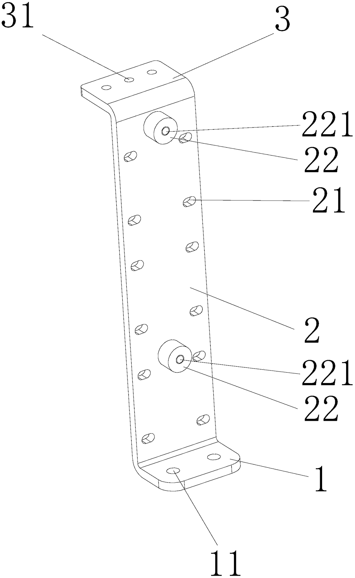
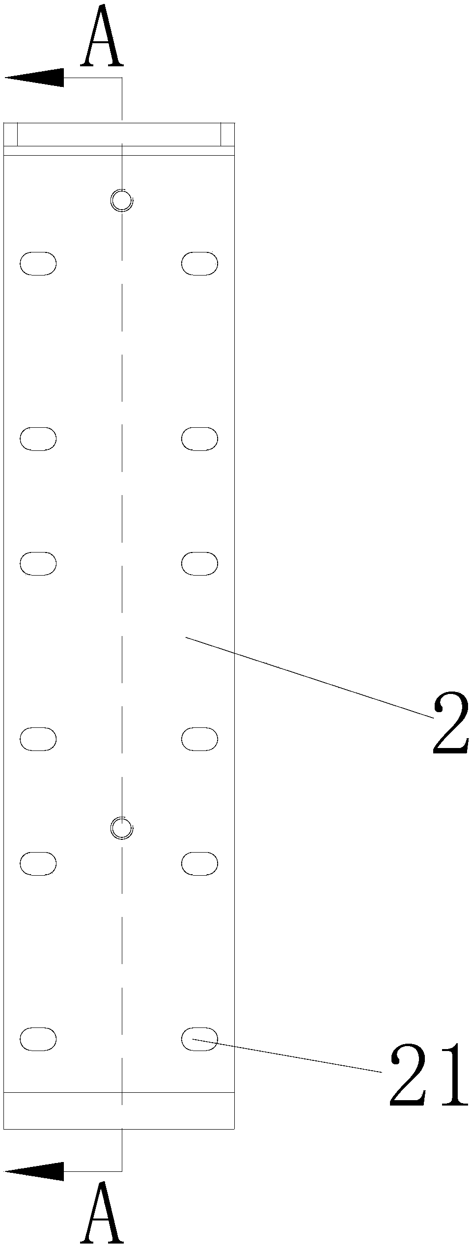
[0035] Such as Figure 1 to Figure 4 As shown, the present embodiment is a battery stack installation bracket, including an installation base plate 1 located at the bottom and a vertical support plate 2 erected from the installation base plate 1, and a plurality of first installation holes 11 are arranged on the installation base plate 1, vertically The support plate 2 is provided with several rows of second mounting holes 21 from bottom to top.

[0036] The top of the vertical support plate 2 is provided with a top support plate 3 , and the top support plate 3 is provided with a plurality of third mounting holes 31 .

[0037] The vertical support plate 2 is also protrudingly provided with several studs 22 , and screw holes 221 are arranged on the studs 22 .

[0038] The number of the studs 22 is two.

[0039] The two studs 22 are spaced up and down.

[0040] The number of the second mounting holes 21 in each row is at least two.

[0041] The installation bottom plate 1 an...

Embodiment 2

[0044] Such as figure 1 , Figure 5 , Image 6 , Figure 7 with Figure 8 As shown, a fuel cell includes a box body 4, a case cover, a stack module 6, a stack mounting bracket 10, a positive bus bar copper bar 7 and a negative bus bar copper bar 8, a stack module 6, a positive bus bar copper bar 7 and The negative busbar copper bar 8 is installed inside the box body 4 through the stack mounting bracket 10. The stack module 6 is formed by stacking several fuel cell cells 60 from bottom to top. The stack mounting bracket 10 described above is the For the stack installation bracket 10 described above, the bottom plate 41 inside the box body 4 is provided with a mounting boss 411, and the mounting bottom plate 1 is installed on the mounting boss 411 through the first mounting hole 11 through screws, and the stack mounting bracket is in the shape of Z The fuel cell unit 60 is locked on the vertical support plate 2 by using screws through the second mounting hole 21, so that the...


PUM


Abstract

The invention discloses a pile mounting bracket and a fuel cell using the same. The pile mounting bracket comprises a mounting bottom plate at the bottom and a vertical supporting plate erected upwardfrom the mounting bottom plate. A plurality of first mounting holes is arranged on the mounting bottom plate, and the vertical supporting plate is provided with a plurality of rows of second mountingholes from bottom to top, and a mounting boss are arranged on the bottom plate inside a case body. The mounting base plate is mounted on the mounting boss by screws through the first mounting hole, and a fuel cell unit is locked to the vertical supporting plate by screws through the second mounting hole. The vertical supporting plate is further provided with a plurality of studs, and the studs are provided with screw holes, and a positive bus bar copper row and a negative bus bar copper bar are all mounted together with an insulating block, and the insulating block is locked on the stud by the screws. The structure of the pile mounting bracket is simple, the module integrated installation is realized, the structure design is reasonable, and the pile mounting bracket has more functions.

Description

Technical field: [0001] The invention relates to an electric stack mounting bracket and a fuel cell using the same. Background technique: [0002] Existing hydrogen energy fuel cells generally include a box, a stack module (that is, a fuel cell stack—that is, a plurality of independent single fuel cells connected in series), a valve group at the inlet of the stack, a valve group at the outlet of the stack, and hydrogen Circulation pump, hydrogen supply system, air system, cooling system, in which stack module, stack inlet valve group, stack gas outlet valve group are all installed in the box, hydrogen supply system, air gas system, cooling system The system is installed outside the box, and the general air system is installed on the bottom plate of the box. A plurality of fuel cell cells are stacked from top to bottom through the stack mounting bracket. The current stack mounting bracket has the following technical problems: 1) the structure is complex, the installation is ...

Claims


Application Information

Patent Timeline
IPC IPC(8): H01M8/2475H01M8/0273
CPCH01M8/0273H01M8/2475Y02E60/50
Inventor 邓佳朱太荣李海君陈星富
Owner BROAD OCEAN MOTOR EV
Why Eureka
Try Eureka