Antenna device and electronic equipment

An antenna device and technology for electronic equipment, applied in the direction of antenna grounding switch structure connection, radiation element structure, etc., can solve problems such as antenna electromagnetic interference, high screen-to-body ratio, and antenna size constraints

Active Publication Date: 2018-11-06
GUANGDONG OPPO MOBILE TELECOMM CORP LTD
View PDF12 Cites 3 Cited by
  • Summary
  • Abstract
  • Description
  • Claims
  • Application Information

AI Technical Summary

Problems solved by technology

[0002] At present, because the metal devices in the mobile phone are likely to cause electromagnetic interference to the antenna, in order to ensure the normal operation of the antenna, the antenna needs to be installed in a clear area
However, the current screen-to-body ratio of mobile phones is getting higher and higher, and the antenna clearance area of ​​full-screen mobile phones has been greatly compressed, resulting in the size of the antenna being restricted, and the radiation performance of the antenna cannot be guaranteed.

Method used


Image

  • Antenna device and electronic equipment
  • Antenna device and electronic equipment
  • Antenna device and electronic equipment

Examples


Embodiment 2

[0043] see Figure 12 , the present application also provides another antenna device 300. The antenna device 300 provided in Embodiment 2 is different from the antenna device 100 provided in Embodiment 1: the first radiator 21 is copper foil. The carrying body 10 includes a middle board 71 , and the display screen module 40 is disposed on one side of the middle board 17 . The middle plate 71 includes a non-metal part 711 and a metal part 712 connected to the non-metal part 711 . The non-metal part 711 is formed in the first clearance area 11 , and the metal part 712 is formed in the non-clean area 12 . The metal portion 712 forms the common ground 14 . The electronic device 200 also includes a backplane 72 . The back plate 72 is fixed on the side of the middle plate 71 facing away from the display module 40 , and the side of the back plate 72 facing the middle plate 71 faces the first headroom 12 and fits the The first radiator 21. In one embodiment, the first radiator 21...

Embodiment 3

[0047] The present application provides another antenna device 400. The antenna device 400 provided in the third embodiment is different from the antenna device 100 provided in the first embodiment: the plurality of resonators 221 include a first radiator coupled to the first radiator 21. A resonator 2211 and a second resonator 2212 coupled to the first feeding source 23 . The multiple resonators 221 further include a third resonator 2213 coupled between the first resonator 2211 and the second resonator 2212 . In this implementation manner, there are multiple third resonators 2213, and two adjacent third resonators 2213 are coupled and connected. In other implementation manners, the number of the third resonator 2213 may also be one.

[0048] In this embodiment, the first radiator 21 is provided with a first coupling portion 212 facing the first resonator 2211 . The first resonator 2211 is provided with a second coupling portion 229 . The second coupling part 229 is coupled...


PUM


Abstract

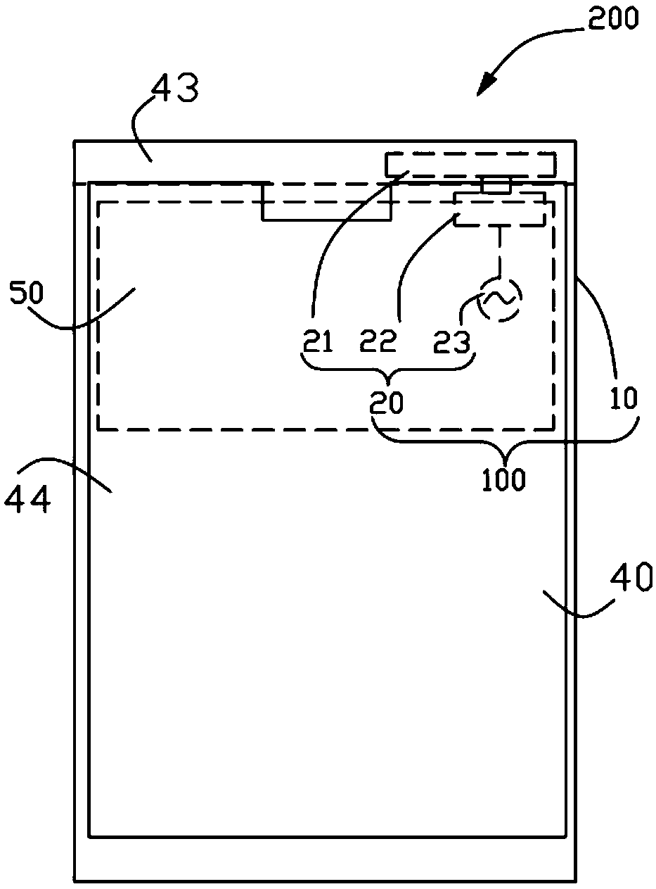
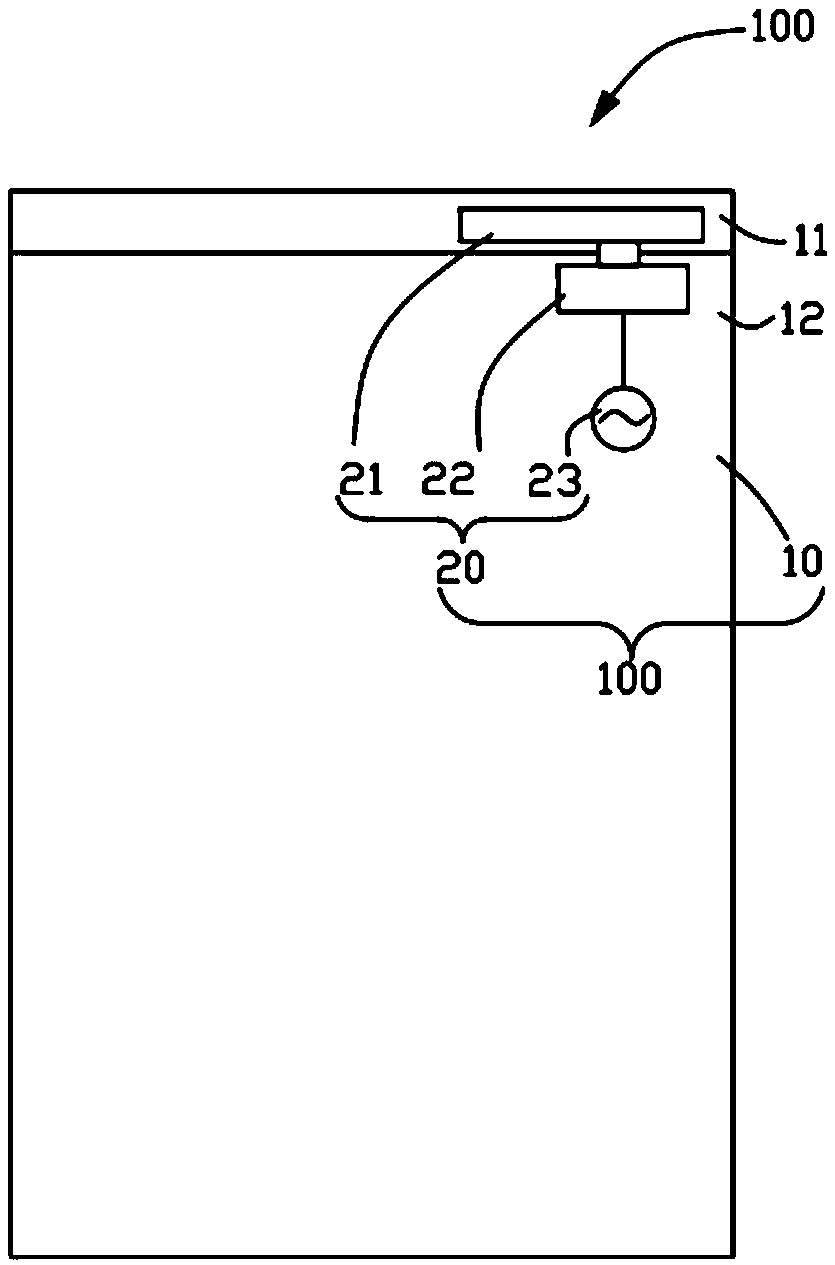
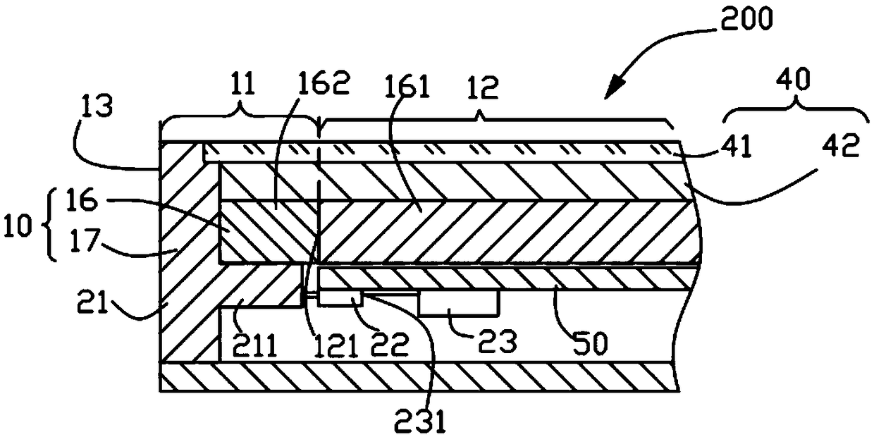
The invention provides an antenna device and electronic equipment. The antenna device comprises a bearing main body and a first antenna module, wherein the first antenna module is fixed relative to the bearing main body, the bearing main body is provided with a first clearance region and a non-clearance region, the non-clearance region is connected with the first clearance region, the first antenna module comprises a first radiation body, a first energy storage part and a first feeding source which are sequentially and electrically connected, at least one part of the positive projection of thefirst radiation body on the bearing main body is arranged on the first clearance region, at least one part of the positive projection of the first energy storage part on the bearing main body is arranged on the non-clearance region, the first feeding source is used for providing feeding energy for the first energy storage part, the feeding energy is stored by the first energy storage part, and the first radiation body is simulated to radiate a signal according to the stored feeding energy. By the antenna device, the occupancy space of the first antenna module on the clearance region is reduced, the occupancy space of the first antenna module on the non-clearance region is expanded, the antenna size is favorably optimized, and the radiation performance of the antenna is ensured.

Description

technical field [0001] The present application relates to the technical field of electronic equipment, and in particular to an antenna device and electronic equipment. Background technique [0002] At present, because the metal devices in the mobile phone are likely to cause electromagnetic interference to the antenna, in order to ensure the normal operation of the antenna, the antenna needs to be installed in a clear area. However, the current screen-to-body ratio of mobile phones is getting higher and higher, and the antenna clearance area of ​​full-screen mobile phones has been greatly compressed, resulting in the size of the antenna being restricted, and the radiation performance of the antenna cannot be guaranteed. Contents of the invention [0003] The present application provides an antenna device. The antenna device includes a carrying body and a first antenna component relatively fixed to the carrying body. The carrying body is provided with a first clearance area...

Claims


Application Information

Patent Timeline
Patent Type & Authority Applications(China)
IPC IPC(8): H01Q1/36H01Q1/50
CPCH01Q1/36H01Q1/50
Inventor 贾玉虎
Owner GUANGDONG OPPO MOBILE TELECOMM CORP LTD
Why Eureka
Try Eureka