A Microstrip Magnetic Dipole Antenna

A magnetic dipole antenna, microstrip technology, applied in the field of antennas, can solve problems such as limiting transmission distance

Active Publication Date: 2019-12-27
SUN YAT SEN UNIV
View PDF9 Cites 0 Cited by
  • Summary
  • Abstract
  • Description
  • Claims
  • Application Information

AI Technical Summary

Problems solved by technology

However, the existing drones often use electric monopole antennas. The advantage of electric monopole antennas is that they can radiate in all directions on the azimuth plane, but the tilt angle between the drone and the ground controller will vary with the flight height and distance. The traditional electric monopole antenna can only produce a conical field with a fixed tilt angle, which limits the transmission distance

Method used


Image

  • A Microstrip Magnetic Dipole Antenna
  • A Microstrip Magnetic Dipole Antenna
  • A Microstrip Magnetic Dipole Antenna

Examples


Embodiment 1

[0035] In this embodiment, the solution of the present invention is described by taking a WLAN frequency band as an example.

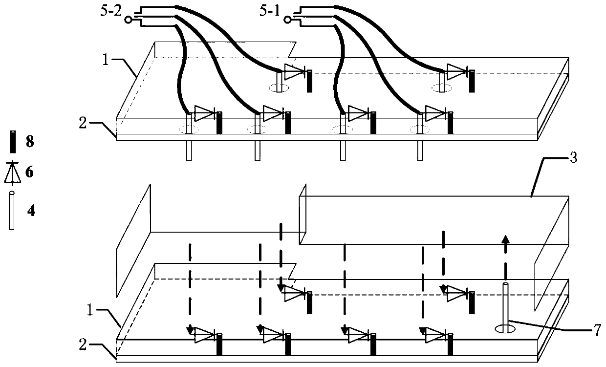
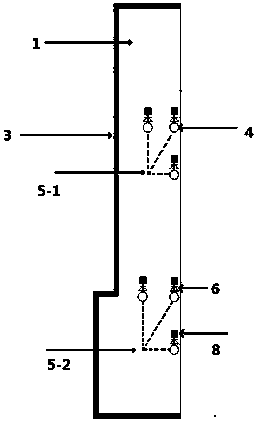
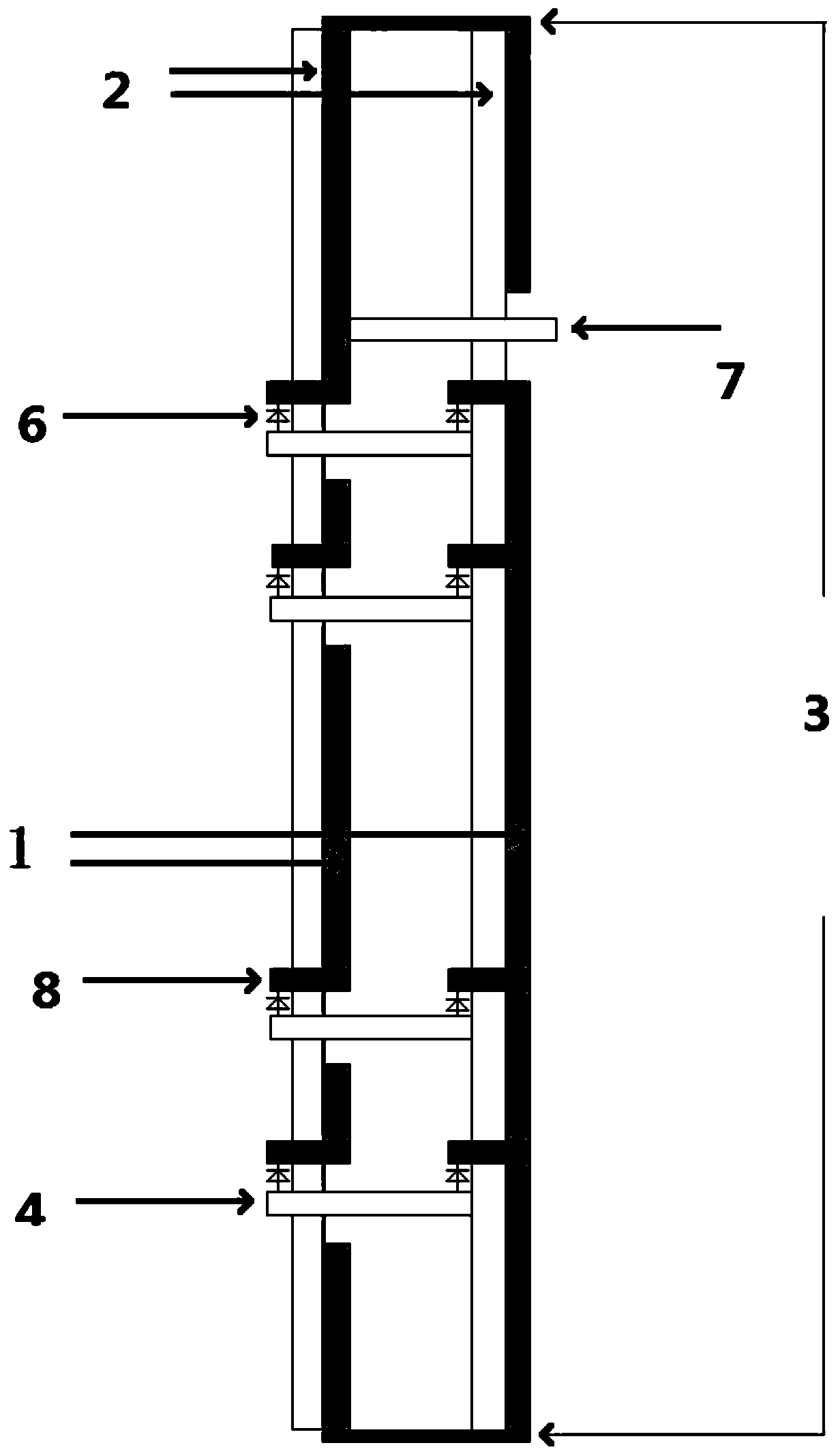
[0036] Such as Figure 1-3 As shown, a microstrip magnetic dipole antenna of the present invention includes two stacked dielectric plates 1, a metal patch 2, a short-circuit wall 3, four groups of short-circuit nails 4, two DC bias lines, a radio frequency switch 6, a feeder Electricity 7 and through hole 8, the backs of the two dielectric boards 1 are respectively covered with metal patches 2;

[0037] Among the four groups of short-circuit nails 4, the first group of short-circuit nails includes a first short-circuit nail and a second short-circuit nail; the second group of short-circuit nails includes a third short-circuit nail, and the third group of short-circuit nails includes a fourth short-circuit nail and a fifth short-circuit nail, The fourth group of shorting pins includes the sixth shorting pins; wherein, the diameter of the shorting pins ...


PUM


Abstract

The invention relates to a microstrip magnetic dipole antenna. The microstrip magnetic dipole antenna comprises two stacked dielectric plates, metal patches, four groups of short circuit pins, two DCbias lines, radio frequency switches, a feed part and through holes formed in the dielectric plate; the back parts of the two dielectric plates are covered with corresponding metal patches respectively; the two ends of each short circuit pin are connected with one end of one corresponding radio frequency switch separately, and the other end of the radio frequency switch is connected to the corresponding metal patch on the back part of the dielectric plate where the radio frequency switch is located through the through hole in the dielectric plate where the radio frequency switch is located; the two groups of short circuit pins front and back are connected with DC bias lines respectively; the first group of short circuit pins and the third group of short circuit pins divide the antenna intothree resonance cavities, wherein the first group of short circuit pins are located between the first resonance cavity and the second resonance cavity, and the third group of short circuit pins are located between the second resonance cavity and the third resonance cavity; the second group of short circuit pins are located in the middle of the second resonance cavity; the fourth group of short circuit pins are located in the middle of the third resonance cavity; and the feed part is located in the first resonance cavity. By virtue of the microstrip magnetic dipole antenna, beam control is realized, so that cone radiation fields with different inclination angles can be obtained.

Description

technical field [0001] The invention relates to the field of antennas, in particular to a microstrip magnetic dipole antenna. Background technique [0002] With the development of artificial intelligence technology, drone technology has entered a stage of rapid development, and drones rely on radio for remote control. However, the existing drones often use electric monopole antennas. The advantage of electric monopole antennas is that they can radiate in all directions on the azimuth plane, but the tilt angle between the drone and the ground controller will vary with the flight height and distance. However, the traditional electric monopole antenna can only produce a conical field with a fixed tilt angle, which limits the transmission distance. Contents of the invention [0003] In order to overcome at least one defect (deficiency) of the above-mentioned prior art, the present invention provides a microstrip magnetic dipole antenna that is easy to process and produce and ...

Claims


Application Information

Patent Timeline
Patent Type & Authority Patents(China)
IPC IPC(8): H01Q1/38H01Q1/50H01Q3/24H01Q9/04
CPCH01Q1/38H01Q1/50H01Q3/247H01Q9/045
Inventor 梁志鹏梁志禧龙云亮
Owner SUN YAT SEN UNIV
Why Eureka
Try Eureka