
Water transfer printing device

A technology of water transfer printing and water tank, which is applied in transfer printing, rotary printing machine, printing, etc., can solve the problems of low efficiency and unfavorable health of workers, so as to improve efficiency, facilitate batch water transfer printing processing, and protect human health Effect

Active Publication Date: 2018-11-09
重庆市魏来雄鑫橡塑制品有限责任公司
View PDF6 Cites 10 Cited by
  • Summary
  • Abstract
  • Description
  • Claims
  • Application Information

AI Technical Summary

Problems solved by technology

[0004] The purpose of the present invention is to provide a water transfer printing device to solve the problems of low efficiency and unfavorable health of workers in the water transfer printing process of auto parts

Method used


Image

  • Water transfer printing device
  • Water transfer printing device

Examples


Embodiment Construction

[0024] The present invention will be described in further detail below by means of specific embodiments:

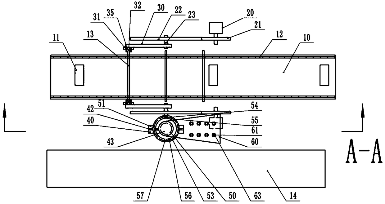
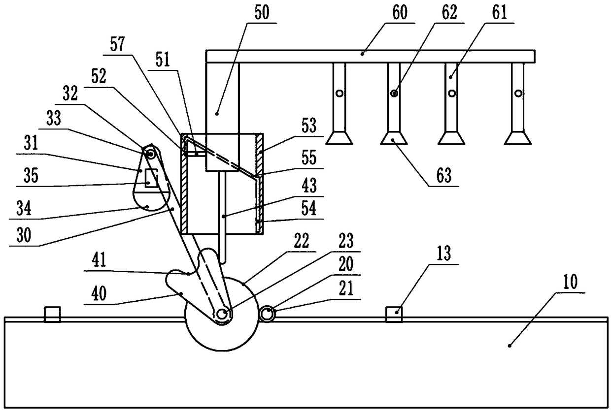
[0025] The reference signs in the accompanying drawings of the description include: water tank 10, roller 11, transmission chain 12, partition bar 13, conveyor belt 14, motor 20, main gear 21, slave gear 22, rotating shaft 23, rotating rod 30, support plate 31, short Shaft 32, bearing 33, counterweight 34, cavity 35, cam 40, groove 41, ring groove 42, slide bar 43, pole 50, slide bar 51, ball 52, sleeve 53, vertical groove 54, circle Ring groove 55, switch 56, short groove 57, grasping plate 60, telescopic rod 61, buckle 62, suction cup 63, figure 1 with figure 2 The middle frame, air pump and air pipe are not shown.

[0026] Such as figure 1 , figure 2 As shown, a water transfer printing device includes a water tank 10, a frame and a conveyor belt 14 parallel to the water tank 10. The bottom of the water tank 10 is provided with a roller 11 that drives the water in...


PUM


Abstract

The invention belongs to the technical field of water transfer printing, and particularly discloses a water transfer printing device. The water transfer printing device comprises a water tank, a rackand a conveying belt parallel to the water tank; idler wheels for driving water in the water tank to flow are arranged at the bottom of the water tank; conveying chains are arranged on the two sides of the water tank correspondingly, and partition rods are clamped on the conveying chains; motors are arranged on the positions, on the two sides of the water tank, of the rack correspondingly, drivinggears are arranged on output shafts of the motors, rotating shafts are rotatably connected to the rack, and the rotating shafts are provided with driven gears engaged with the driving gears; rotatingrods are fixed to the rotating shafts, and supporting plates are hinged to the ends, away from the rotating shafts, of the rotating rods; counterweight blocks are hinged to the lower ends of the supporting plates, and concave cavities are formed in the positions, at the upper ends of the counterweight blocks, of the supporting plates; the two concave cavities corresponding to the two motors are symmetrically formed facing the water tank; and the distances between the supporting plates and the rotating shafts are not less than the distance between the two partition rods. Compared with the prior art, the water transfer printing device can automatically and continuously conduct water transfer printing machining on automobile parts, the efficiency of water transfer printing batch machining isgreatly improved, and the health of workers is also protected.

Description

technical field [0001] The invention belongs to the technical field of water transfer printing, and specifically discloses a water transfer printing device. Background technique [0002] Water transfer printing technology is a printing technology that uses water pressure to hydrolyze the patterned transfer paper / plastic film with polymers, and then coats it on the surface of the product. With the improvement of people's requirements for product packaging and decoration, the use of water transfer printing is becoming more and more extensive. The principle of indirect water transfer printing and the perfect printing effect have solved the problems of surface decoration of many products. At present, water transfer printing technology has been widely used in auto parts. [0003] At present, auto parts are being processed by water transfer printing. In order to achieve batch continuous processing, a slow-flowing water tank is used to hydrolyze the required water transfer pattern...

Claims


Application Information

Patent Timeline
Patent Type & Authority Applications(China)
IPC IPC(8): B41F16/00
CPCB41F16/00
Inventor 熊强
Owner 重庆市魏来雄鑫橡塑制品有限责任公司
Learn More