
Low-power-consumption intelligent door lock and low-power-consumption standby method thereof

A smart door lock and low power consumption technology, which is applied in building locks, lock applications, electric number locks, etc., can solve the problems of increased power consumption, complex functions, and high comprehensive power consumption of locks, and achieve comprehensive energy consumption reduction. The effect of reasonable structural design

Active Publication Date: 2018-11-09
TIANJIN TIANYOU TECH
View PDF7 Cites 4 Cited by
  • Summary
  • Abstract
  • Description
  • Claims
  • Application Information

AI Technical Summary

Problems solved by technology

The functions of existing smart door locks are becoming more and more complex. The addition of functions such as fingerprints, bluetooth, keyboards, and IC cards increases the power consumption of locks and shortens the cycle of replacing batteries for locks. Once there is no power, smart locks will not be able to open the door. In particular, door locks with low door opening frequency often fail to open the door. Therefore, it is necessary to design a low-power smart door lock and develop a matching method to reduce the power consumption of the door lock to reduce the power consumption of the door lock and extend the battery life. Life in the lock, prolonging the cycle of battery replacement
[0003] After the analysis of the working principle of the smart door lock, it is believed that the high power consumption of the smart door lock is mainly due to the high comprehensive power consumption of each subsystem of the fingerprint module, Bluetooth module, key module, and IC card module. Standby power consumption is not large, but multiple sub-modules standby at the same time results in multiple power consumption, especially when the smart door lock is unused for a long time, these consumptions become waste

Method used


Image

  • Low-power-consumption intelligent door lock and low-power-consumption standby method thereof

Examples


Embodiment Construction

[0011] In order to further understand the content of the invention, features and effects of the present invention, the following examples are given in detail as follows:

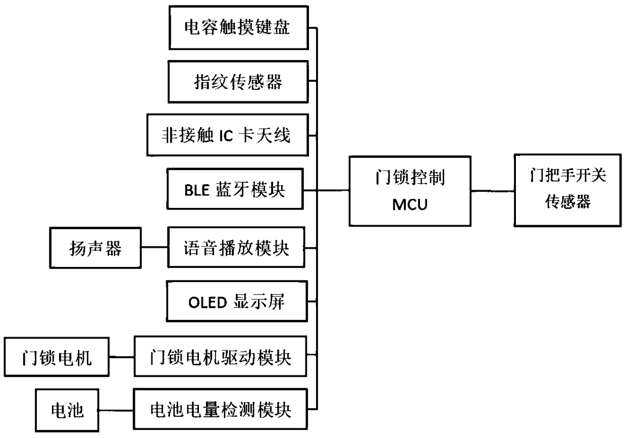
[0012] See figure 1 , the low-power intelligent door lock of the present invention includes a door lock control MCU, a capacitive touch keyboard, a fingerprint sensor, a non-contact IC card antenna, a BLE Bluetooth module, a voice playback module, an OLED display screen, a door lock motor drive module, and a battery power monitoring Module and door handle switch sensor, capacitive touch keyboard, fingerprint sensor, non-contact IC card antenna, BLE Bluetooth module, voice playback module, OLED display, door lock motor drive module, battery power monitoring module and door handle switch sensor are all connected with the door The lock control MCU is electrically connected; it also includes a loudspeaker, a door lock motor and a battery, the loudspeaker is electrically connected to the voice playback module, th...


PUM


Abstract

The invention relates to a low-power-consumption intelligent door lock. The low-power-consumption intelligent door lock comprises a door lock control MCU, a capacitance touch keyboard, a fingerprint sensor, a non-contact IC card antenna, a BLE module, a voice playing module, an OLED display screen, a door lock motor driving module, a battery capacity monitoring module and a door handle switch sensor, and further comprises a loudspeaker, a door lock motor and a battery. A low-power-consumption standby method comprises the steps that (1) the door lock is closed; (2) after 5 seconds, the BLE module, the voice playing module, the OLED display screen, the door lock motor driving module and the battery capacity monitoring module are turned off, and the capacitance touch keyboard, the fingerprintsensor and the non-contact IC card antenna are reserved to be turned on; (3) when the door lock control MCU monitors the situation that the door handle switch sensor does not transmit a signal for continuous 48 hours, the capacitance touch keyboard, the fingerprint sensor and the non-contact IC card antenna are turned off; (4) during door opening, the handle switch sensor transmits the signal tothe door lock control MCU, and the capacitance touch keyboard, the fingerprint sensor and the non-contact IC card antenna are turned on; and (5) the door lock is opened.

Description

technical field [0001] The invention belongs to the technical field of intelligent door locks, in particular to a low-power intelligent door lock and a low-power standby method thereof. Background technique [0002] With the advancement of technology and the improvement of people's living standards, there are more and more solutions for people's home security. Among them, smart door locks, as an important link, have a very important impact on home security and convenience. The functions of existing smart door locks are becoming more and more complex. The addition of functions such as fingerprints, bluetooth, keyboards, and IC cards increases the power consumption of locks and shortens the cycle of replacing batteries for locks. Once there is no power, smart locks will not be able to open the door. In particular, door locks with low door opening frequency often fail to open the door. Therefore, it is necessary to design a low-power smart door lock and develop a matching metho...

Claims


Application Information

Patent Timeline
IPC IPC(8): E05B47/00E05B49/00G07C9/00
CPCE05B47/0012E05B49/00E05B2047/0053E05B2047/0065G07C9/00563
Inventor 贺晓龙王玉莹蒋宏伟
Owner TIANJIN TIANYOU TECH
Learn More