Supercharge Your Innovation With Domain-Expert AI Agents!

Magnetic hysteresis compensation control method for magnetorheological damper

A magneto-rheological damper and hysteresis compensation technology, applied in the field of hysteresis compensation, can solve problems such as few solutions, failure to achieve control effects, and neglect of system parameters, so as to meet the requirements and suppress negative effects

Inactive Publication Date: 2018-11-09
NANJING FORESTRY UNIV
View PDF6 Cites 4 Cited by
  • Summary
  • Abstract
  • Description
  • Claims
  • Application Information

AI Technical Summary

Problems solved by technology

At present, the existing nonlinear research on magnetorheological dampers is mainly from the dynamic point of view, and the hysteresis nonlinear modeling or control between the damping force and velocity of magnetorheological dampers is carried out, while the magnetorheological damping There are few solutions to the hysteresis nonlinear problem caused by the magnetization of ferromagnetic materials. To overcome this problem, the common method is to establish the hysteresis model of the magnetorheological damper and integrate it into the control method, although the mathematical model can Characterize hysteresis nonlinearity, but this open-loop control method ignores the changes in system parameters after modeling, and cannot achieve ideal control effects

Method used


Image

  • Magnetic hysteresis compensation control method for magnetorheological damper
  • Magnetic hysteresis compensation control method for magnetorheological damper
  • Magnetic hysteresis compensation control method for magnetorheological damper

Examples


Embodiment Construction

[0045] The embodiments of the present invention will be described in detail below in conjunction with the accompanying drawings, so that the advantages and features of the present invention can be more easily understood by those skilled in the art, so as to define the protection scope of the present invention more clearly.

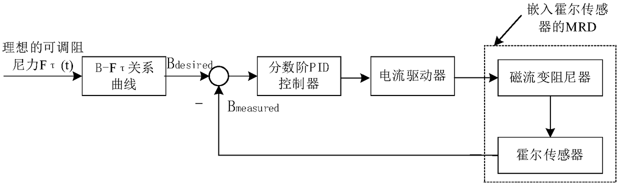
[0046] The invention provides a hysteresis compensation method for a magneto-rheological damper, comprising the steps of:

[0047] (1) Install the magneto-rheological damper in the impact buffer control system it uses, and calculate the target adjustable damping force F of the magnetorheological damper according to the impact buffer control requirements τ ;

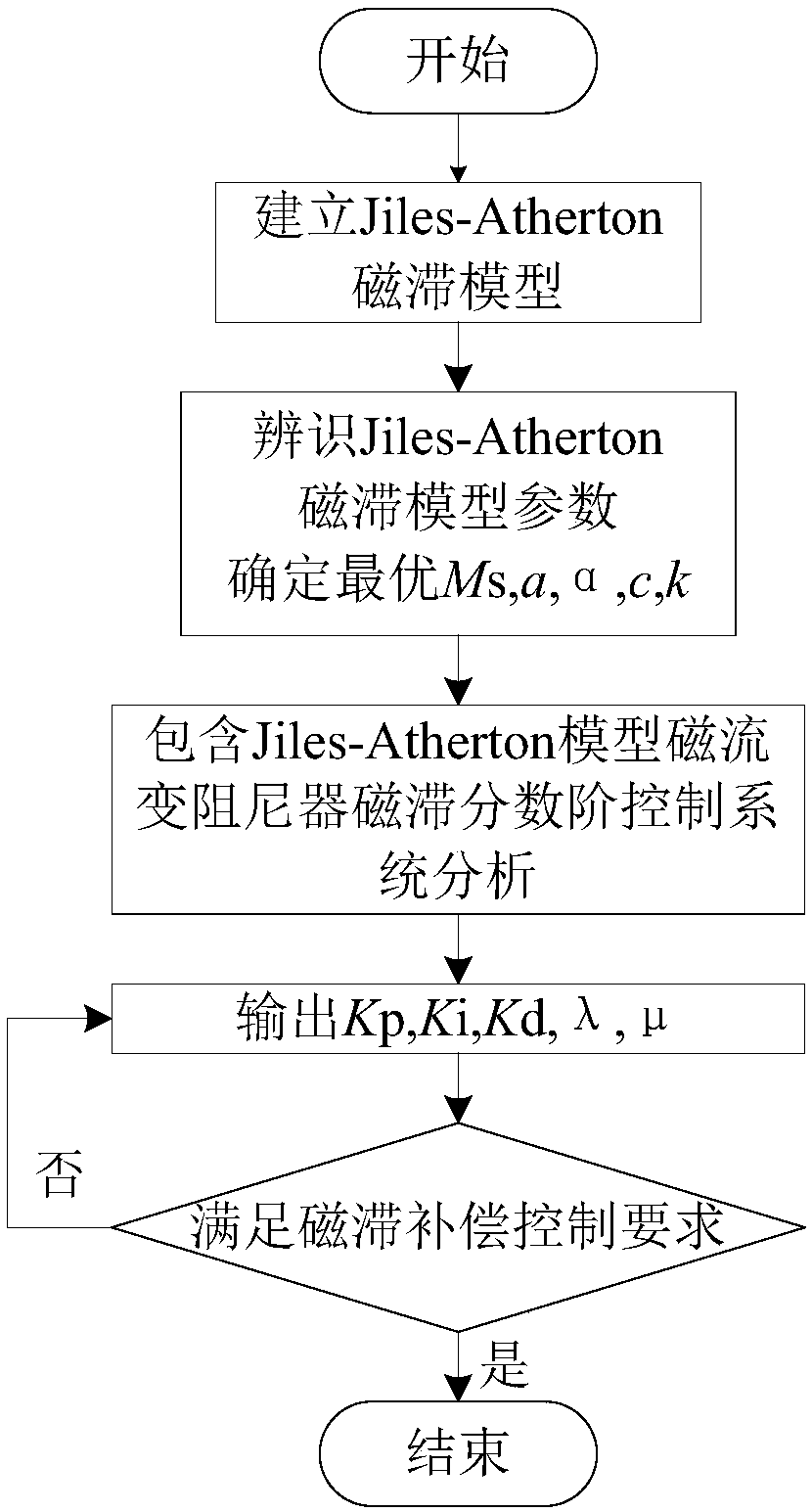
[0048] (2) Calculate the corresponding target magnetic induction intensity according to the target adjustable damping force and the structural design parameters of the magnetorheological damper. The calculation steps are as follows:

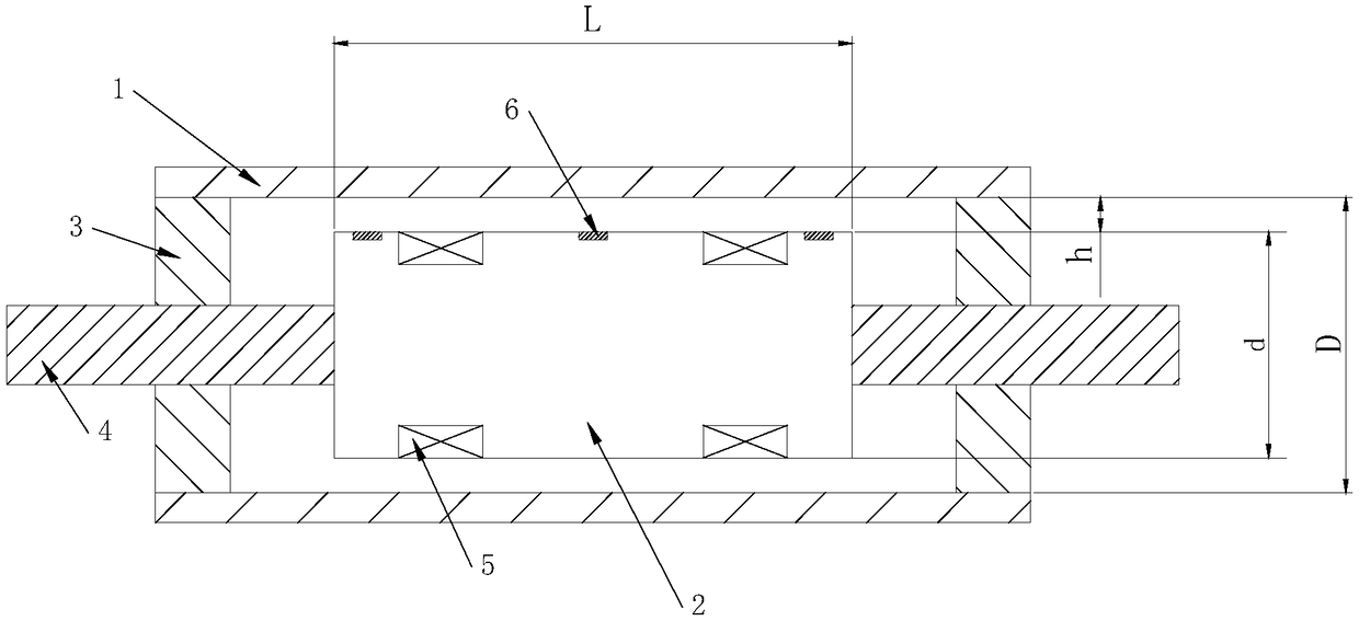
[0049] According to the structure and working principle of the magne...


PUM


Abstract

The invention discloses a magnetic hysteresis compensation method for a magnetorheological damper. The magnetic hysteresis compensation method comprises the steps that on the basis of target adjustable damping force, the corresponding target magnetic induction intensity is calculated according to design parameters of the magnetorheological damper; a Hall sensor is embedded into a damping channel of the magnetorheological damper, and the magnetic induction intensity for perpendicularly penetrating through magnetorheological fluid in the damping channel is detected in real time; the error between the target magnetic induction intensity and the detected magnetic induction intensity serves as input of a fractional order PID controller; and output of the fractional order PID controller is transmitted to a current driver, the current driver generates corresponding currents to be led into a magnet exciting coil of the magnetorheological damper, a magnetic induction intensity closed-loop control system is constituted, thus the actual magnetic induction intensity tracks the target magnetic induction intensity, and magnetic hysteresis compensation control is achieved. In this way, accordingto the magnetic hysteresis compensation method for the magnetorheological damper, the negative influences of the magnetic hysteresis nonlinear characteristics of the magnetorheological damper on the response speed and control accuracy of an impact buffer control system are suppressed.

Description

technical field [0001] The invention relates to the field of vibration control based on a magneto-rheological damper, in particular to a method for realizing hysteresis compensation by using multi-point embedded Hall sensors to measure magnetic induction intensity and fractional-order control theory. Background technique [0002] The magnetorheological damper is a new type of intelligent device made by using the magnetorheological fluid to realize the continuous and reversible transformation between liquid, viscous body and semi-solid within milliseconds under the action of an external magnetic field. The advantages of simple structure, continuously controllable damping force and large adjustable range, fast response speed and low energy consumption are gradually being applied in the fields of vehicle engineering, civil engineering and weapon systems. However, the inherent hysteresis nonlinearity of the magnetorheological damper limits its wide application in engineering, an...

Claims


Application Information

Patent Timeline
IPC IPC(8): F16F9/53
CPCF16F9/535F16F2224/045F16F2230/18
Inventor 李赵春王皖君龚瑶
Owner NANJING FORESTRY UNIV
Features
  • R&D
  • Intellectual Property
  • Life Sciences
  • Materials
  • Tech Scout
  • Unparalleled Data Quality
  • Higher Quality Content
  • 60% Fewer Hallucinations
Learn More