Rigid solid quick shutdown radar transmitter modulation device and method

A transmitter and fast technology, applied in radio wave measurement systems, instruments, etc., can solve problems such as difficult to meet requirements, limited MOS tube junction capacitance discharge time, and unsatisfactory problems, to protect the modulator and prevent overcurrent from burning out the modulation device, reducing the effect of internal resistance

Active Publication Date: 2018-11-09
HAIHUA ELECTRONICS ENTERPRISECHINA CORP
View PDF14 Cites 1 Cited by
  • Summary
  • Abstract
  • Description
  • Claims
  • Application Information

AI Technical Summary

Problems solved by technology

The disadvantage of the linear modulator is that the modulated pulse width is determined by the pulse forming network, also known as the artificial line and the artificial line. In this way, under the limitation of the maximum working ratio of the point vacuum, the change of the pulse width and repetition frequency is restricted, and it is difficult to meet the requirements of modern radars for emission. machine requirements
[0003] At present, although the rigid modulator can flexibly change the pulse width and repetition frequency under the limitation of the maximum working ratio of the electric vacuum tube, the power level of the modulator cannot be increased, and it cannot meet the requirements of modern radars for transmitters.
And the ordinary rigid modulation technology relies on the effective signal period of the trigger control signal pulse to control the opening and closing of the modulator, that is, under normal circumstances, the closing is limited by the discharge time of the junction capacitance of the MOS tube, and it cannot be accurately and quickly closed for debugging.

Method used


Image

  • Rigid solid quick shutdown radar transmitter modulation device and method
  • Rigid solid quick shutdown radar transmitter modulation device and method
  • Rigid solid quick shutdown radar transmitter modulation device and method

Examples


Embodiment

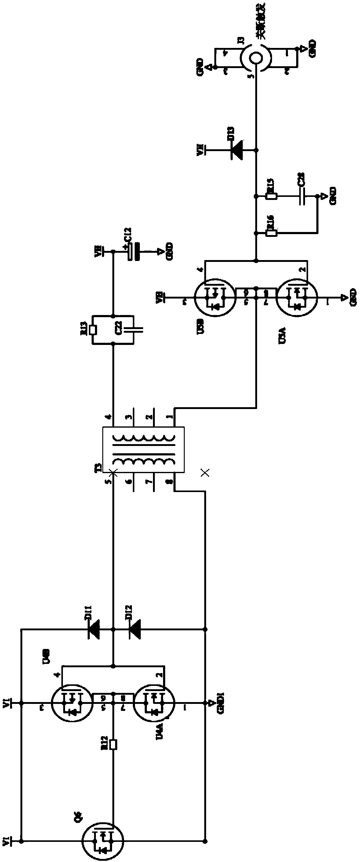
[0034] A rigid solid-state fast turn-off radar transmitter modulation device, such as figure 1 As shown, it includes an opening circuit, an closing circuit, a pulse transformer, and a vacuum tube. The opening circuit includes multiple MOS tubes connected in parallel, one end of the opening circuit is connected to the opening trigger, and the other end is connected to the pulse transformer; circuit, a pulse isolation transformer circuit, a third MOS tube drive circuit, a shutdown-high-speed MOS tube; the isolation drive circuit is connected to the shutdown trigger, the pulse isolation transformer is powered by a power supply, the third MOS tube drive circuit, the shutdown Off - the high-speed MOS tube is powered by an isolated power supply; the closing circuit and the opening circuit connect the pulse transformer to the vacuum tube.

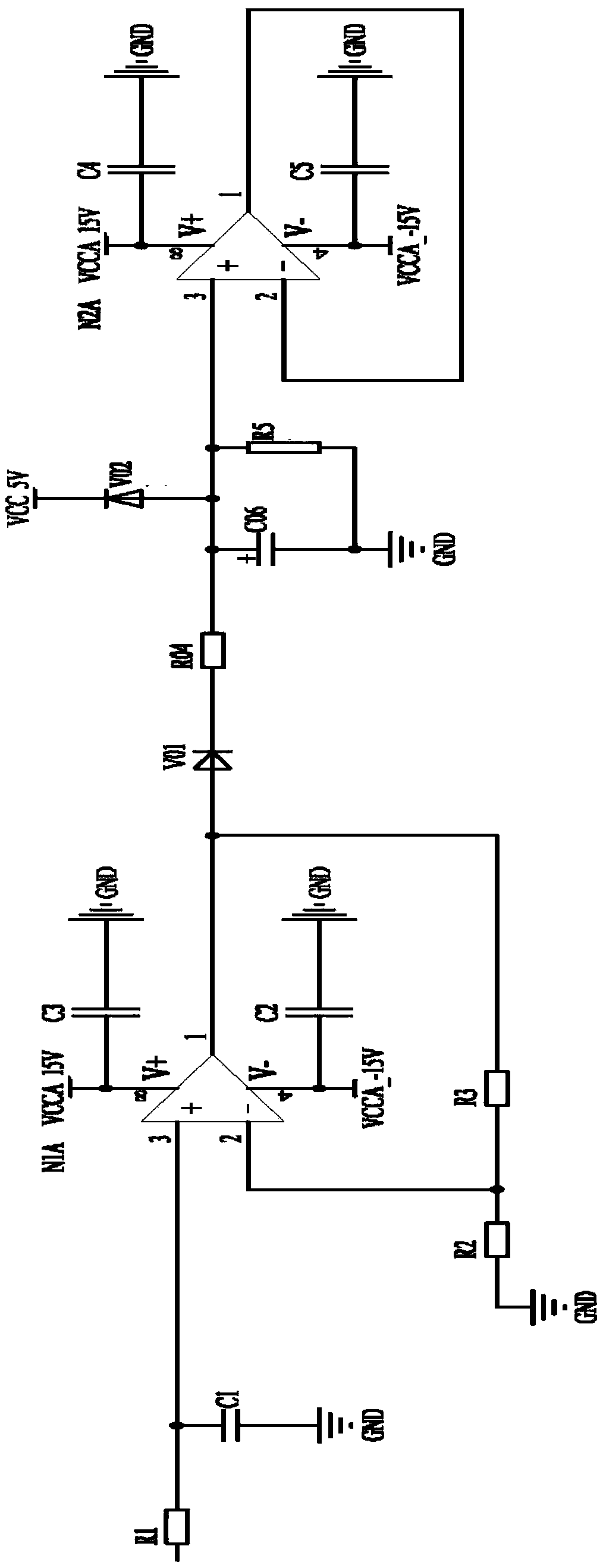
[0035] In order to protect the circuit, a vacuum tube overcurrent detection circuit is added behind the vacuum tube to connect with the vacuum tu...


PUM


Abstract

The invention discloses a rigid solid quick shutdown radar transmitter modulation device comprising a starting circuit, a shutdown circuit, a pulse transformer and a vacuum tube. The starting circuitcomprises multipath MOS transistors which are connected in parallel. The starting circuit is connected with the starting trigger and the pulse transformer. The shutdown circuit comprises an isolationdriving circuit, a pulse isolation transformer circuit, a third MOS transistor driving circuit and a shutdown-high-speed MOS transistor which are connected in turn. The isolation driving circuit is connected with the shutdown trigger. The shutdown circuit and the starting circuit are connected with the pulse transformer and the vacuum tube. Multipath MOS transistors are connected in parallel to complete shunting and reduce internal resistance, and the starting circuit MOS transistor is controlled to be conducted through the starting trigger pulse and the starting time of the MOS transistor iscontrolled. The primary side of the pulse transformer is controlled to be shut down through the shutdown trigger pules and the shutdown circuit MOS transistor is controlled to be conducted so that quick shutdown can be realized, the pulse width can be accurately controlled and control of different pulse widths and different repetition frequencies can be realized.

Description

technical field [0001] The invention relates to the research field of pulse modulation, in particular to a modulation device and method for a rigid solid-state rapid shutdown radar transmitter. Background technique [0002] There are two types of radar pulse modulators, namely linear modulators and rigid modulators. The disadvantage of the linear modulator is that the modulated pulse width is determined by the pulse forming network, also known as the artificial line and the artificial line. In this way, under the limitation of the maximum working ratio of the point vacuum, the change of the pulse width and repetition frequency is restricted, and it is difficult to meet the requirements of modern radars for emission. machine requirements. [0003] At present, although the rigid modulator can flexibly change the pulse width and repetition frequency under the limit of the maximum working ratio of the electric vacuum tube, the power level of the modulator cannot be increased, a...

Claims


Application Information

Patent Timeline
Patent Type & Authority Applications(China)
IPC IPC(8): G01S7/282
CPCG01S7/282
Inventor 黄占伟易先林詹涛
Owner HAIHUA ELECTRONICS ENTERPRISECHINA CORP
Why Eureka
Try Eureka