
Work vehicle and travel region specification device

A technology for driving areas and working vehicles, applied in vehicle position/route/height control, agriculture, motor vehicles, etc., can solve the problems of increased labor for operators and inability to start work immediately, and achieve good efficiency.

Active Publication Date: 2018-11-09
YANMAR POWER TECHNOLOGY CO LTD
View PDF10 Cites 8 Cited by
  • Summary
  • Abstract
  • Description
  • Claims
  • Application Information

AI Technical Summary

Problems solved by technology

[0007] Therefore, in the past, it was necessary for the operator to return to other accompanying work vehicles after arranging the work vehicle at the work start position, so that there was a problem that the work could not be started immediately after the work vehicle was arranged. When the positions are separated, the labor required for the movement of the operator increases

Method used


Image

  • Work vehicle and travel region specification device
  • Work vehicle and travel region specification device
  • Work vehicle and travel region specification device

Examples


no. 1 approach

[0299] Figure 25 An embodiment is shown in which the order of the working paths is determined by skipping two paths toward one side from the working path R1 at the end (work start position S), and from the limit of one side, that is, when one cannot move toward one side. Skip 2 working roads R10 and return to the first working road R2 adjacent to the working road R1 at the end, from here skip 2 roads to one side again to set the running order of the working roads, when reaching the limit After that, return to the second working road R3 adjacent to the working road R1 at the end, and skip two roads to one side again to set the running order of the working roads. Also, the "travel order" is the travel order in the work route Ra generated on the route R, which is the order of the work roads for traveling in the work route Ra from one headland HB to another headland HB.

[0300] Figure 26 This shows an embodiment in which the order of the working lanes is determined by skippin...

no. 2 approach

[0311] Figure 29 An embodiment in which the work start position is changed according to the number of work lanes is shown. Figure 29 , the upper part shows an example where the number of working lanes is set to 12 (a multiple of 3), the middle part shows an example where the number of working lanes is set to 10 (a multiple of 3 - 2), and the lower part shows an example of An example in which the number of work paths is set to 11 (a multiple of 3 - 2) is shown.

[0312]When the number of working roads is 3N (N is a natural number above 4, "3N" is a multiple of 3), the second working road R2 starting from the end is taken as the starting position, When the number is 3N-2, the third working lane R3 from the end is set as the starting position, and when the number of working lanes is 3N-1, the working lane R1 at the end is set as the starting position. Then, after the work start position S (work road to start) is set according to the number of work roads, the running order of ...


PUM


Abstract

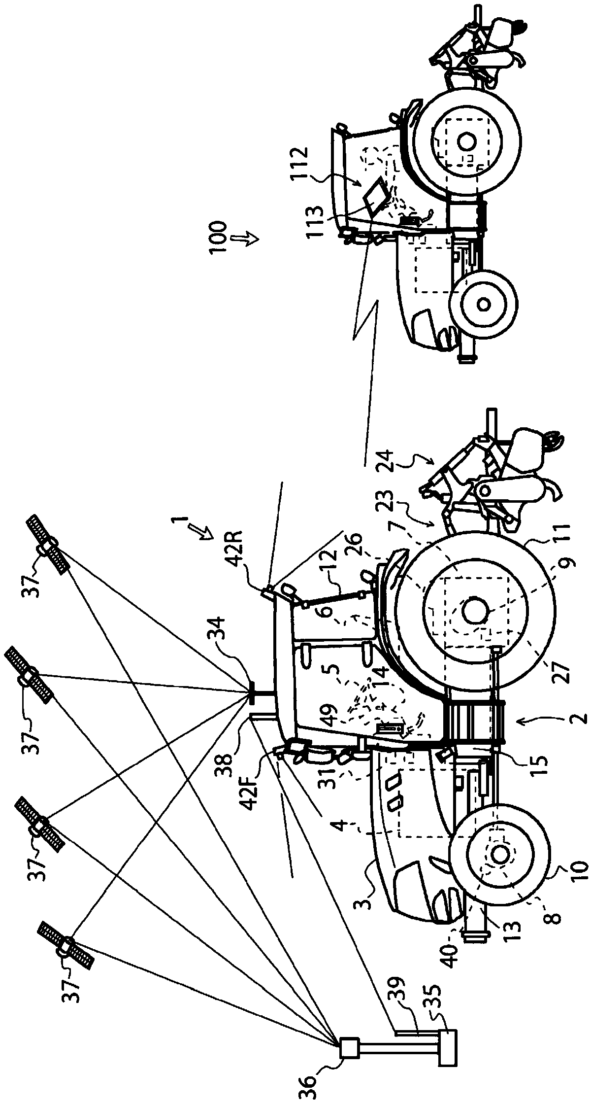
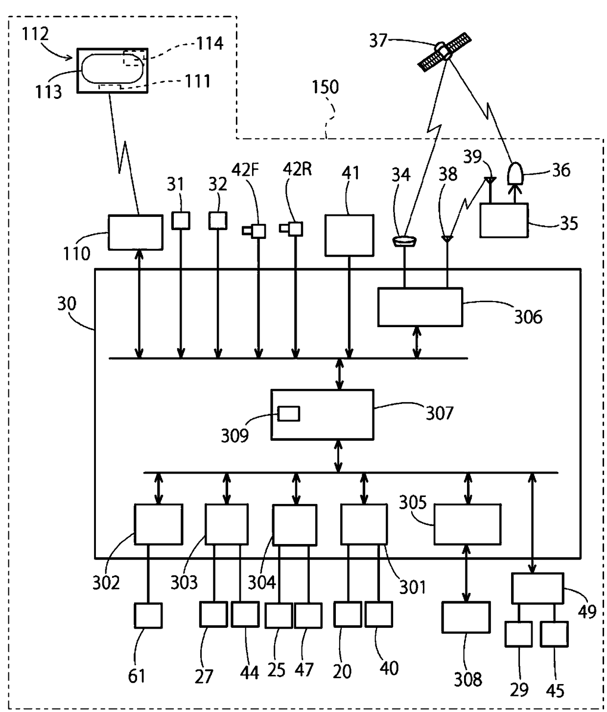
The purpose of the present invention is to reduce the burden of an operation for disposing an autonomous-travel work vehicle in a work start position, and to improve work efficiency. An autonomous travel work vehicle 1 is provided with: a vehicle body 2; a work machine 24 mounted on the vehicle body 2; a mobile GPS antenna 34 with which it is possible to detect position information of the vehiclebody 2; a memory 309 with which it is possible to store a farm field H in which the vehicle body 2 is caused to travel; a control unit 30 with which it is possible to control the travel of the vehiclebody 2 within the farm field H, and the work by the work machine 24; and a remote operation device 112 for generating a route R of the vehicle body 2 in the farm field H. The farm field H includes awork region HA that includes a work route Ra in which the work is performed by the work machine 24, and headlands HB that are set at the periphery of the work region HA, and when the start of the workby the work machine 24 in the headland HB is ordered, the control unit 30 causes the vehicle body 2 to travel from the current position Z of the vehicle body 2 to a work start position Sw, after which the work can be started by the work machine 24.

Description

technical field [0001] The present invention relates to a technology of a working vehicle and a driving area determining device. Background technique [0002] Conventionally, work vehicles such as tractors are known that can autonomously travel (unmanned travel) along a set route. For example, there is a work vehicle disclosed in Patent Document 1. [0003] The work vehicle disclosed in Patent Document 1 is equipped with a control program for defining work routes in the work area (central part of the work site) where the work vehicle is used for work, and in areas other than the work area (peripheral part). The work vehicle autonomously travels along the work route through the program, thereby enabling the automation of predetermined work. [0004] patent documents [0005] Patent Document 1: Japanese Patent Application Laid-Open No. 10-66405 Contents of the invention [0006] However, in the conventional autonomously traveling work vehicle as disclosed in Patent Docume...

Claims


Application Information

Patent Timeline
Patent Type & Authority Applications(China)
IPC IPC(8): A01B69/00G05D1/02
CPCG05D1/02A01B69/00G05D1/0219G05D1/0291A01B69/008G05D1/43G05D1/648G05D1/644G05D1/248G05D2105/15G05D2101/10G05D1/0088G05D1/027G05D1/0278
Inventor 平松敏史
Owner YANMAR POWER TECHNOLOGY CO LTD
Learn More