
Method for setting up a rotary processing machine and rotary processing machine

A processing machine tool and turning technology, which is applied in the field of setting up turning machine tools and turning machine tools, can solve the problems of expensive, expensive setting, error-prone, etc., and achieve the effect of low cost and fast method

Inactive Publication Date: 2018-11-09
J G WEISSER SOHNE
View PDF7 Cites 0 Cited by
  • Summary
  • Abstract
  • Description
  • Claims
  • Application Information

AI Technical Summary

Problems solved by technology

However, additional processing steps are required for this, which are likewise costly and expensive
[0008] What all these methods of this setup have in common is that they inevitably involve manual method steps and therefore cannot or are difficult to automate
The setting up of turning machines is correspondingly expensive, labor-intensive and error-prone

Method used


Image

  • Method for setting up a rotary processing machine and rotary processing machine
  • Method for setting up a rotary processing machine and rotary processing machine
  • Method for setting up a rotary processing machine and rotary processing machine

Examples


Embodiment Construction

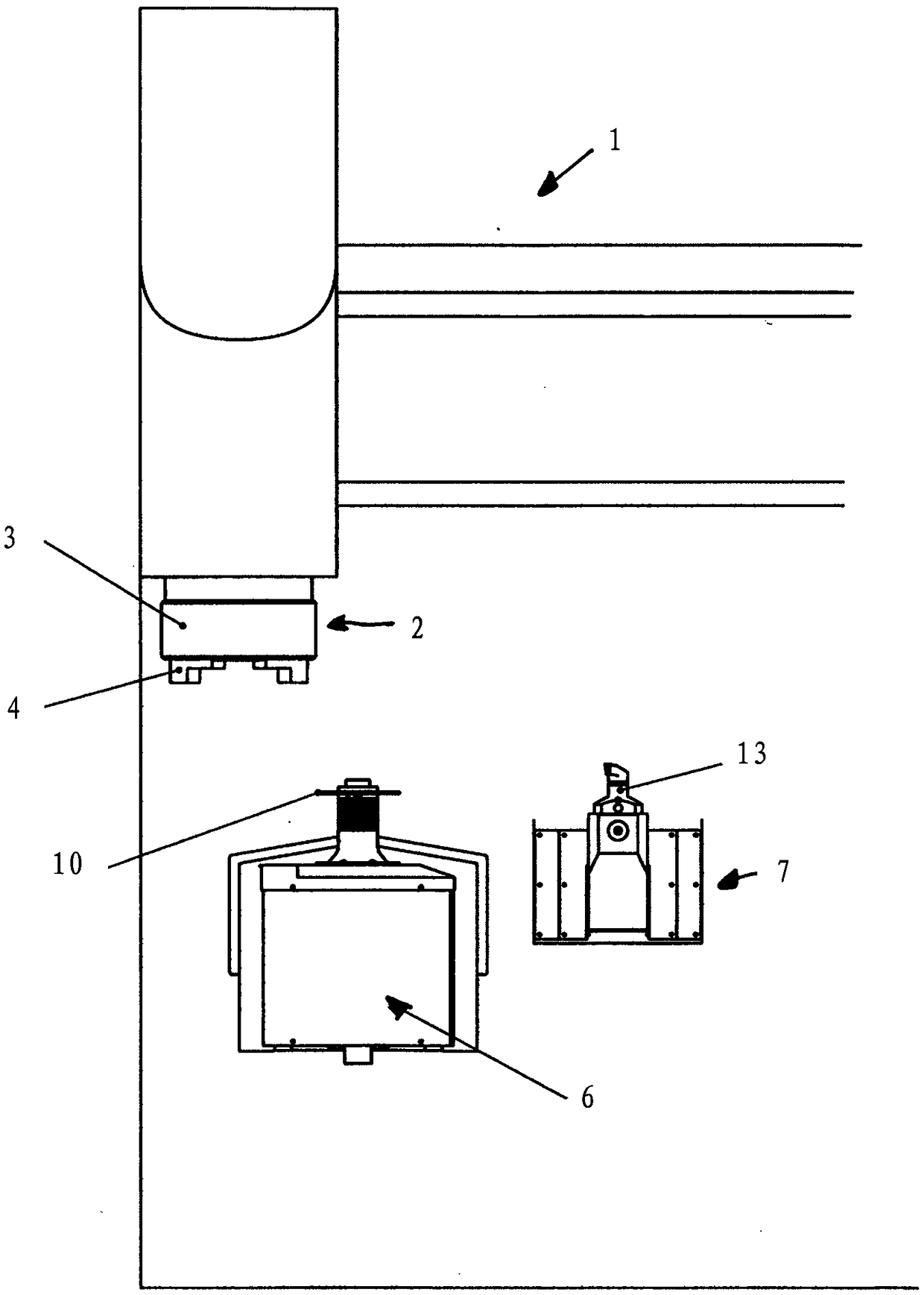
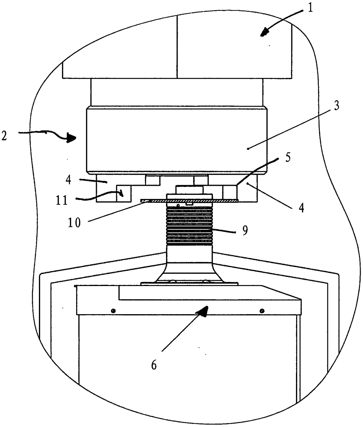
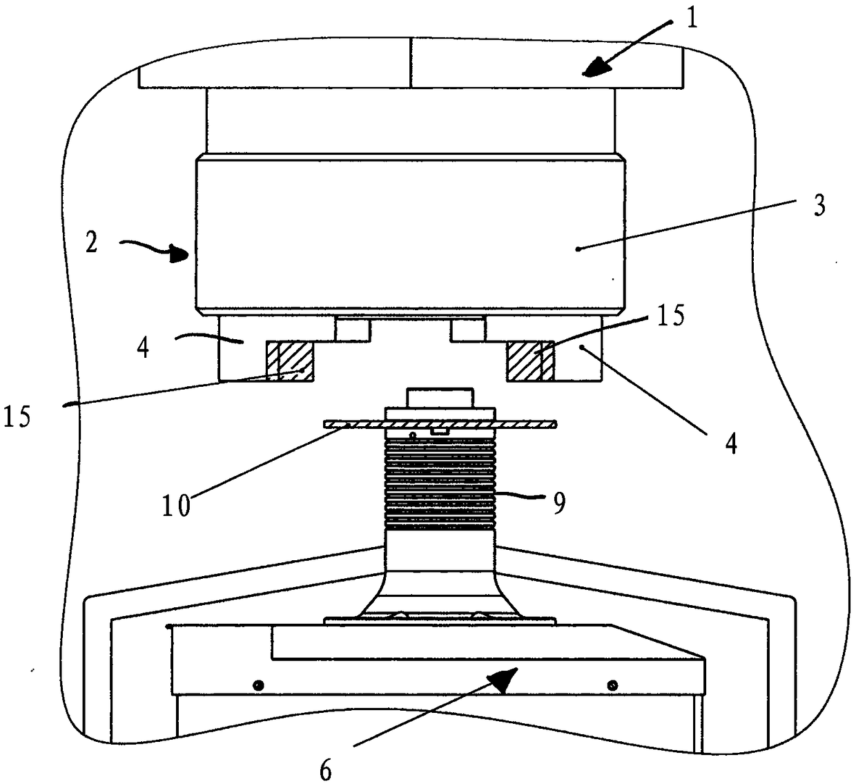
[0040] figure 1 A turning machine tool according to the invention, denoted as a whole by 1 , hereinafter referred to simply as a lathe, is shown. The lathe 1 has a workpiece holder 2 which is designed, for example, as a so-called three-jaw lathe chuck 3 . On the lathe chuck 3 three base jaws 4 are arranged radially at an angular distance of 120° from one another, of which only two base jaws 4 are shown in the figure for a better overview.

[0041] The base jaw 4 mainly has a square shape extending in the radial direction and has an axial step 5 . The base jaw 4 can be oriented in the radial direction on the lathe chuck 3 in order to clamp a workpiece. Such a base jaw 4 is a standard part of the lathe 1 and is available in different shapes and embodiments. Therefore, there are also base jaws 4 without axial steps 5 , or base jaws 4 with two or more axial steps 5 . Likewise, lathe chucks 2 with more than three base jaws 4 also exist.

[0042] Furthermore, the lathe 1 has a ...


PUM


Abstract

The invention relates to a method for setting up a rotary processing machine (1), in which at least one base jaw (4) of a workpiece receptacle is set up to receive a workpiece type that is to be processed and in which the base jaw (4) is coated on a workpiece contact surface (15).

Description

technical field [0001] The invention relates to a method for setting a turning machine tool, wherein the base jaws of the workpiece holder are arranged for clamping a workpiece type to be machined, and to a method, in particular for carrying out the method according to the invention, A turning machine tool with a workpiece holder having at least one base jaw. Background technique [0002] Such turning machines for machining workpieces are known. Here, the workpiece is firmly clamped in a workpiece holder which is rotatable relative to a substantially stationary tool. There are different clamping mechanisms for securely clamping a workpiece in a workholding fixture, which can be selected according to the shape and nature of the workpiece. [0003] A common shape for such a workholding fixture is a circular lathe chuck with jaw receptacles that can be fixed in different radial positions for clamping a workpiece. Usually these jaws have locking elements which cooperate with ...

Claims


Application Information

Patent Timeline
IPC IPC(8): B23B25/06
CPCB23B31/10B23B25/00B23B2228/10B23B25/06B23K26/354B23K2101/34B05D5/10B23K26/34
Inventor T·雷蒂希
Owner J G WEISSER SOHNE
Learn More