Check patentability & draft patents in minutes with Patsnap Eureka AI!

Drive unit

A technology of drive unit and drive slot, which is applied in the direction of automatic control devices, machine tool parts, precision positioning equipment, etc., to achieve the effects of improving efficiency and service life, reducing energy consumption, and suppressing undesired movements

Inactive Publication Date: 2018-11-09
WESEE LTD
View PDF5 Cites 1 Cited by
  • Summary
  • Abstract
  • Description
  • Claims
  • Application Information

AI Technical Summary

Problems solved by technology

[0004] A disadvantage of the known drive units is that the drive always has to be fully ready for operation in order to be able to directly implement the received control signals

Method used


Image

  • Drive unit

Examples


Embodiment Construction

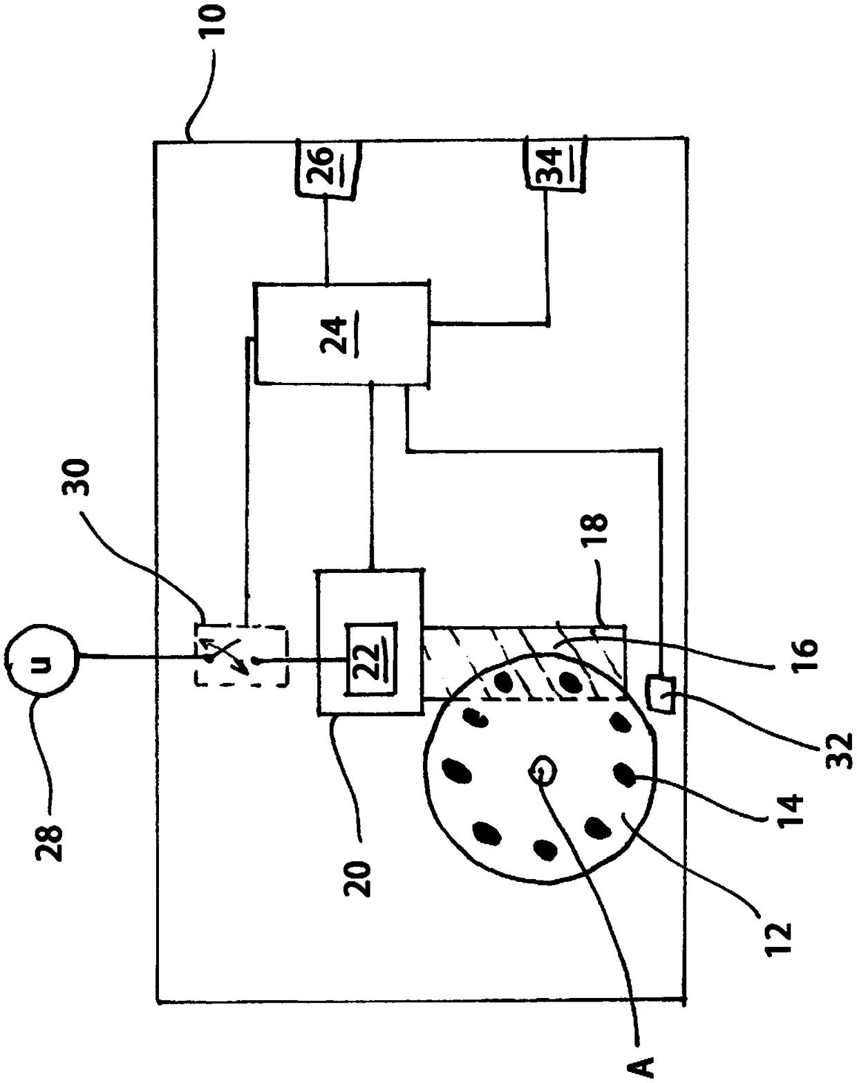
[0032] The drive unit 10 , here in particular a rotary indexing table, comprises a transfer element which is configured as a turntable 12 and is rotatable about an axis A extending perpendicularly to the plane of the drawing. The turntable 12 has a plurality of entrainers 14 which are distributed in the circumferential direction and which, depending on the rotational position of the turntable 12 , engage into drive grooves of a barrel cam 18 rotatable perpendicular to the axis A.

[0033] The drive unit 10 also includes an electric drive 20 having an electric motor 22 mechanically coupled to the barrel cam 18 . The driving device 20 is electrically connected to the base control device 24 .

[0034] The base control means 24 is adapted to receive control signals for the operation of the drive unit 10 from the operator programmable user interface 26, and to output the drive signals to the drive means 20 or to apply the required current thereto in accordance with the received con...


PUM


Abstract

A drive unit having a transport element has an electrical drive device and a basic control device. The transport element has at least one driver engaging in a drive slot of a cam drum. The basic control device is adapted to receive control signals for operating the drive unit from a user interface which can be programmed by an operator and to output a drive signal to the drive device on the basisof a received control signal. The drive device is adapted to drive the cam drum to perform a rotational movement and to therefore drive the transport element in response to the drive signal. The basiccontrol device is also adapted to selectively operate the drive device in a full operating mode or, if a control signal is not received after a drive signal has been output and after the expiry of acycle time of the drive unit, to change the drive device to a standby operating mode in which an electrical supply for the drive device is interrupted.

Description

technical field [0001] The invention relates to a drive unit having a transfer element with at least one entrainer engaging in a drive groove of a barrel cam, having an electric drive, and having a base control device. Various types of drive units can be configured, such as so-called rotary indexing tables, where the transfer element can be a turntable and the drive means can be an electric motor coupled directly or indirectly to a barrel cam. For example, the turntable on which the object to be machined is positioned can be rotated in this way between the desired machining positions by means of an electric motor. Background technique [0002] The base control means is adapted to receive control signals for operation of the drive unit from the operator-programmable user interface, and to output drive signals to the drive means in accordance with the received control signals. The drive means is adapted to drive the barrel cam for rotational movement and thus drive the transf...

Claims


Application Information

Patent Timeline
IPC IPC(8): B23Q15/26B23Q16/02
CPCB23Q15/013B23Q16/025B23Q2220/004
Inventor 阿诺德·霍恩
Owner WESEE LTD
Features
  • R&D
  • Intellectual Property
  • Life Sciences
  • Materials
  • Tech Scout
  • Unparalleled Data Quality
  • Higher Quality Content
  • 60% Fewer Hallucinations
Learn More