Objective Optical System
A technology of optical system and objective lens, which is applied in the field of objective lens optical system, can solve the problems of reduced contrast, unsatisfactory, etc., and achieve the effect of reducing the driving amount of the lens
- Summary
- Abstract
- Description
- Claims
- Application Information
AI Technical Summary
Problems solved by technology
Method used
Image

Examples
no. 1 approach
[0041] The objective optical system related to the first embodiment is composed of a front group, a middle group, and a rear group arranged in order from the object side,
[0042] The focal length is changed by moving the intermediate group along the optical axis, and the objective optical system is characterized in that,
[0043] In either of the far-point observation state and the near-point observation state, the following conditional expressions (1) and (2) are satisfied.
[0044] |(1 / 2)×βf×βt×((1 / βf)-1)|≤0.055 (1)
[0045] 0.12≤Sa / FL≤0.44 (2)
[0046] in,
[0047] βf is the lateral magnification of the middle group,
[0048] βt is the lateral magnification of the rear group,
[0049] Sa is the movement amount of the middle group,
[0050] FL is the focal length of the objective optical system,
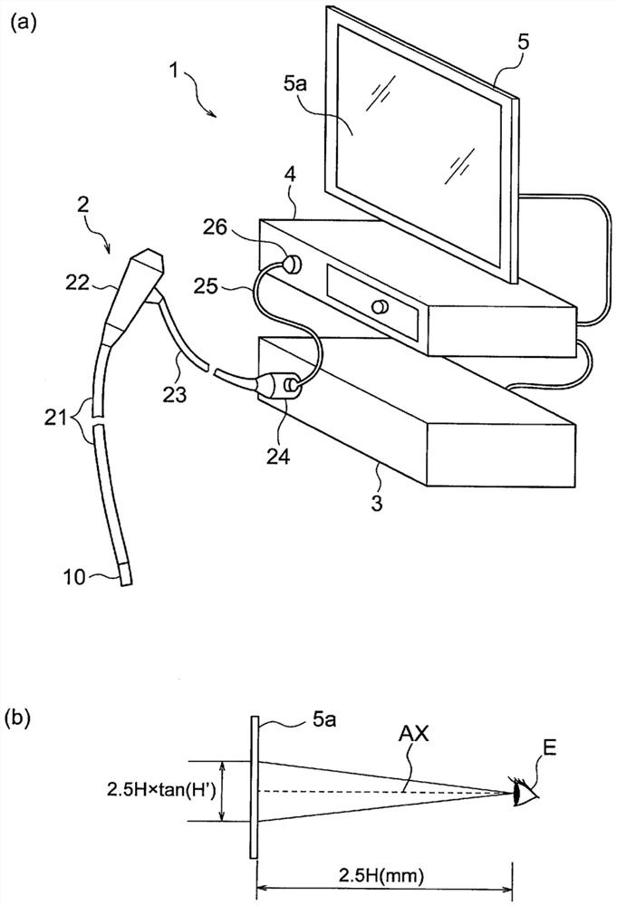
[0051] The conditional expressions (1) and (2) are conditional expressions for the far-point observation state (the object distance is 60 mm) and the conditional expressions...
Embodiment 1
[0123] The objective optical system according to Example 1 will be described. Figure 4 (a) is a lens cross-sectional view of the objective optical system according to this embodiment in a far-point observation state. Figure 4 (b) is a lens cross-sectional view in a close-point observation state of the objective optical system according to this embodiment.
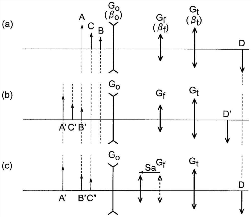
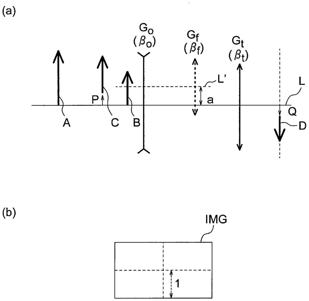
[0124] The present embodiment has a front group Go of negative refraction power, an intermediate group Gf of positive refraction power, and a rear group Gt of positive refraction power arranged in this order from the object side.
[0125] The front group Go is composed of a negative meniscus lens L1 with a convex surface facing the object side, a biconcave negative lens L2, and a biconvex positive lens L3. The negative lens L2 is cemented with the positive lens L3.
[0126] The middle group Gf is composed of a filter F1, a brightness stop S, and a plano-convex positive lens L4 that directs the plane toward the object si...
Embodiment 2
[0130] In the objective optical system according to Example 2, the lens diameter is reduced by making the value of the conditional expression (2) near the lower limit, that is, reducing the lens drive amount of the intermediate group Gf. However, on the other hand, the smaller the driving amount of the middle group Gf is, the larger the difference between the optimal object position in the paraxial region of the right-eye optical system and the optimal object position in the paraxial region of the left-eye optical system is. .
[0131] For example, when the working distance is around 60 mm to 100 mm during stereoscopic viewing, and the difference between the optimal object position of the left-eye optical system and the optimal object position of the right-eye optical system is 10 mm or more, the optimal object for stereoscopic images The position cannot be fixed, resulting in the inability to perform fine medical actions based on stereo vision correctly.
[0132] When the po...
PUM
 Abstract
Description
Claims
Application Information
PatSnap Eureka turns technology decisions into work you can execute. Powered by our Innovation Knowledge Graph, it runs expert workflows across engineering, life sciences, materials and intellectual property. Get your review-ready output in minutes.


