Centrifugal pulp screening machine with high pulp screening efficiency

A high-efficiency, centrifugal technology, applied in centrifuges and other directions, can solve the problems affecting the efficiency of pulp screening and affecting the effect of pulp screening, and achieve the effect of improving screening effect, ingenious structure and high practicability

Active Publication Date: 2018-11-13
NINGBO QIXIN TECH CO LTD
6 Cites 2 Cited by

AI-Extracted Technical Summary

Problems solved by technology

[0003] The existing centrifugal sieve must work under full load, if it works under less than full load, it will affect the effect of sieving, not only t...

Method used

As preferably, in order to facilitate feeding, the top of described connecting box 14 is provided with air inlet, can avoid the too low air pressure in connecting box 14 and influence feeding speed by air inlet, has realized the function of being convenient to feeding.
As preferably, in order to improve tightness, described rotating shaft is provided with sealing ring, and described sealing ring is set on transmission shaft 8, and the bottom end of described main body 1 is set ...

Abstract

The invention relates to a centrifugal pulp screening machine with high pulp screening efficiency. The centrifugal pulp screening machine comprises a main body, a discharging pipe and four supports; the discharging pipe is arranged on one side of the main body, and the supports are uniformly arranged at the bottom end of the main body; a control mechanism is arranged in the main body, and a feeding mechanism is arranged at the top end of the main body; the control mechanism comprises a driving assembly, a control assembly and an auxiliary assembly; the driving assembly comprises a driving motor, a driving wheel, a driven wheel, a driving belt, a transmission shaft, a rotating disc, a fixing plate, a sleeve, blades and at least two screens; the feeding mechanism comprises a detection assembly and two feeding assemblies; and the detection assembly comprises a connecting box, a lifting rod, a connecting plate and a floating ball. According to the centrifugal pulp screening machine with the high pulp screening efficiency, the screening efficiency is improved through the control mechanism, in addition, the function of full-load operation is achieved through the feeding mechanism.

Application Domain

Centrifuges

Technology Topic

Drive motorDrive wheel +2

Image

  • Centrifugal pulp screening machine with high pulp screening efficiency
  • Centrifugal pulp screening machine with high pulp screening efficiency
  • Centrifugal pulp screening machine with high pulp screening efficiency

Examples

  • Experimental program(1)

Example Embodiment

[0025] The present invention will now be described in further detail with reference to the drawings. These drawings are all simplified schematic diagrams, which merely illustrate the basic structure of the present invention in a schematic manner, so they only show the structures related to the present invention.
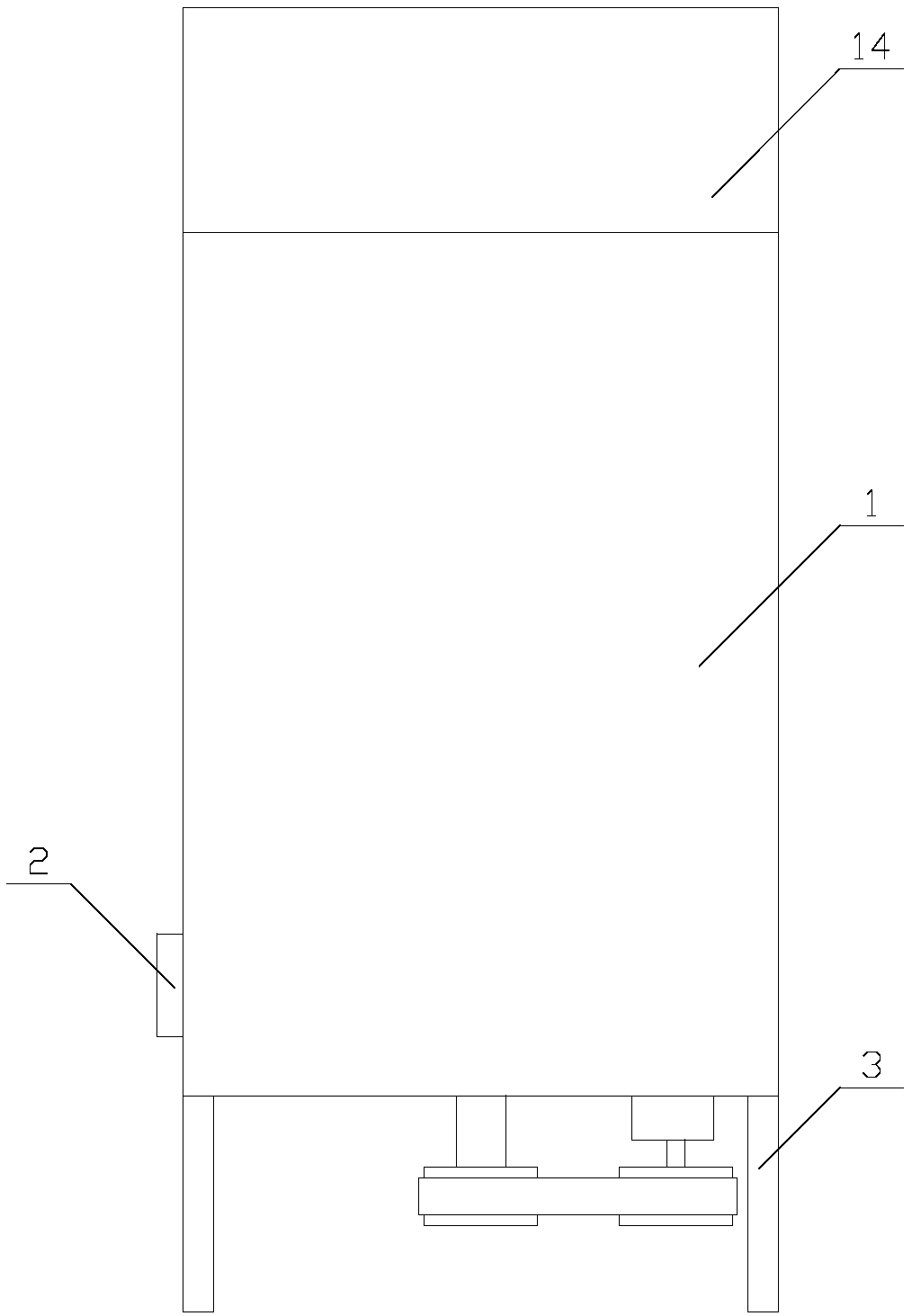
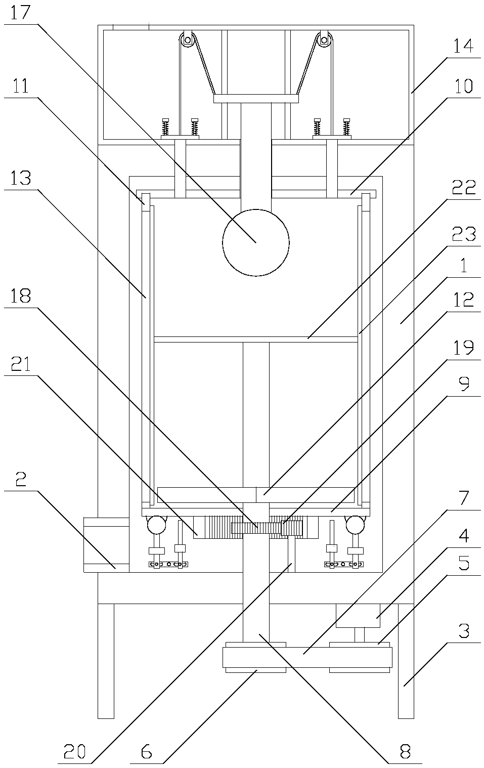
[0026] Such as Figure 1-2 As shown, a centrifugal screener with high screening efficiency includes a main body 1, a discharge tube 2 and four brackets 3. The discharging tube 2 is arranged on one side of the main body 1, and the brackets 3 are evenly arranged At the bottom end of the main body 1, a control mechanism is provided in the main body 1, and a feeding mechanism is provided at the top of the main body 1;
[0027] The equipment improves the screening effect through the control mechanism, and realizes the function of full-load operation through the feeding mechanism.
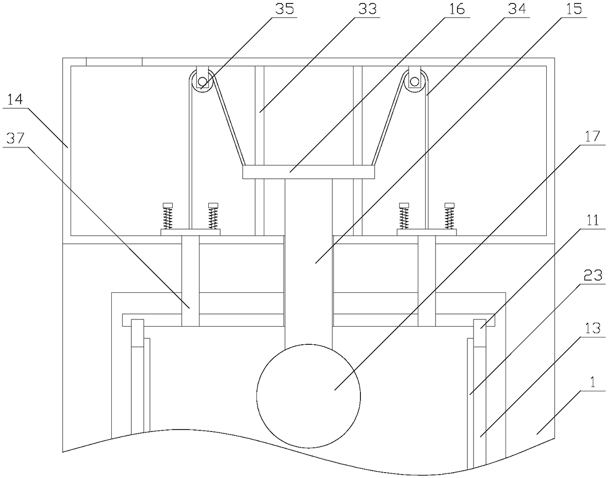
[0028] Such as figure 2 As shown, the control mechanism includes a drive assembly, a control assembly and an auxiliary assembly. The drive assembly includes a drive motor 4, a drive wheel 5, a driven wheel 6, a transmission belt 7, a transmission shaft 8, a rotating disk 9, a fixed plate 10, and a sleeve. The barrel 11, the paddle 12 and at least two screens 13, the drive motor 4 is fixed at the bottom end of the main body 1, the drive motor 4 is drivingly connected with the drive wheel 5, the drive shaft 8 is vertically arranged, the The bottom end of the main body 1 is sleeved on the transmission shaft 8, the driven wheel 6 is sleeved on the bottom end of the transmission shaft 8, the driving wheel 5 and the driven wheel 6 are respectively provided at both ends of the inner side of the transmission belt 7, the rotation The disc 9 and the fixed plate 10 are both horizontally arranged in the main body 1, the rotating disc 9 is sleeved on the transmission shaft 8, the fixed plate 10 is fixedly connected to the main body 1, the fixed plate 10 is arranged above the rotating disc 9 , The sleeve 11 and the transmission shaft 8 are arranged coaxially, the sleeve 11 and the paddle 12 are both arranged between the fixed plate 10 and the rotating disk 9, and the bottom end of the sleeve 11 is fixedly connected to the rotating disk 9 , The bottom end of the fixed plate 10 is provided with an annular groove, the top end of the sleeve 11 is arranged in the annular groove, the blade 12 is installed on the transmission shaft 8, and the sleeve 11 is provided with at least two Openings, the openings correspond to the screen 13 one-to-one, and the screen 13 is arranged in the opening;
[0029] The driving motor 4 runs to make the driving wheel 5 rotate. The driving wheel 5 rotates the driven wheel 6 through the transmission belt 7 and drives the transmission shaft 8 to rotate, so that the blade 12 drives the raw material to rotate, and the function of screening impurities is realized by centrifugal force.
[0030] Such as image 3 As shown, the feeding mechanism includes a detection component and two feeding components. The detection component includes a connecting box 14, a lifting rod 15, a connecting plate 16, and a float 17. The connecting box 14 is arranged at the top of the main body 1, so The connecting box 14 is provided with raw materials, the lifting rod 15 is arranged vertically, the bottom end of the connecting box 14 is sleeved on the lifting rod 15, and the top end of the main body 1 is sleeved on the lifting rod 15. The fixing plate 10 is sleeved on the lifting rod 15, the floating ball 17 is fixed at the bottom end of the lifting rod 15, the connecting plate 16 is horizontally arranged in the connecting box 14, and the top end of the lifting rod 15 is fixed on the connecting plate 16. At the bottom end, two feeding components are respectively arranged on both sides of the lifting rod 15.
[0031] When the raw material in the main body 1 decreases, the floating ball 17 is lowered and the lifting rod 15 is driven to lower, so that the connecting plate 16 is lowered. The lowering of the connecting plate 16 causes the feeding assembly to operate, realizing the function of driving the feeding assembly.
[0032] Preferably, in order to improve the efficiency of screening, the control assembly includes a drive gear 18, a connecting gear 19, a fixed shaft 20, an internal gear 21, a rotating rod 22, and two scraping rods 23. The drive gear 18 is sleeved on the transmission shaft. 8, the drive gear 18 meshes with the connecting gear 19, the fixed shaft 20 is arranged vertically, the connecting gear 19 is sleeved on the top end of the fixed shaft 20, and the fixed shaft 20 is fixed at the bottom end of the main body 1. , The connecting gear 19 meshes with the internal gear 21, the internal gear 21 is fixed at the bottom end of the rotating disk 9, the rotating rod 22 is horizontally arranged at the top end of the transmission shaft 8, the scraping rod 23 is vertically arranged, two Two scraping rods 23 are respectively fixed on both ends of the rotating rod 22, the scraping rod 23 is attached to the screen 13, and the driving gear 18 is rotated by the rotation of the transmission shaft 8, and the driving gear 18 drives the connecting gear 19 to rotate, and the connecting gear 19 The internal gear 21 drives the rotating disc 9 to rotate, so that the rotation of the rotating disc 9 is opposite to that of the transmission shaft 8. The rotation of the rotating disc 9 drives the sleeve 11 to rotate, and the rotation of the transmission shaft 8 causes the rotating rod 22 to drive the scraper bar 23 in the screen. The screen 13 moves on, so that the scraper rod 23 will scrape the impurities on the screen 13 and improve the efficiency of screening.
[0033] Such as Figure 4 As shown, the auxiliary assembly includes two auxiliary units and at least two hemispherical blocks 24. The hemispherical blocks 24 are evenly arranged on the outer circumference of the transmission shaft 8 in the circumferential direction, and the side of the hemispherical block 24 away from the spherical surface is fixed in rotation. At the bottom end of the disc 9, two auxiliary units are respectively arranged on both sides of the transmission shaft 8. The rotation of the rotating disc 9 causes the hemispherical block 24 to rotate around the transmission shaft 8, and the rotation of the hemispherical block 24 makes the auxiliary unit run, which realizes The function of driving the auxiliary unit.
[0034] Preferably, in order to vibrate the screen 13, the auxiliary unit includes a connecting ball 25, a connecting rod 26, a fixed block 27, a supporting block 28, a connecting rod 29, a rubber rod 30, a supporting rod 31 and two power rods 32, so The connecting rod 29 is arranged horizontally, the middle end of the connecting rod 29 is sleeved on the supporting rod 31, the axis of the supporting rod 31 is perpendicular to the axis of the connecting rod 29, and the axis of the supporting rod 31 is perpendicular to the axis of the transmission shaft 8. The axis is vertical, the support rod 31 is fixed on the inner wall of the main body 1, the connecting rod 29 is provided with sliding grooves on both sides, and the two power rods 32 are respectively arranged in the two sliding grooves. The axis is parallel to the axis of the support rod 31, the connecting rod 26 and the rubber rod 30 are both vertically arranged, and the two power rods 32 are respectively fixedly connected to the bottom end of the connecting rod 26 and the bottom end of the rubber rod 30. The connecting ball 25 is fixed at the top end of the connecting rod 26, the connecting ball 25 is arranged between two adjacent hemispherical blocks 24, the top end of the connecting ball 25 abuts against the bottom end of the rotating disk 9, and the fixing block 27 is sleeved On the connecting rod 26, the supporting block 28 is sleeved on the rubber rod 30, the fixed block 27 and the supporting block 28 are both fixed on the inner wall of the main body 1, and the connecting ball 25 is pushed down by the rotation of the hemispherical block 24 , The connecting rod 26 drives the power rod 32 connected with the connecting rod 26 to push the connecting rod 29 to rotate on the support rod 31, so that the power rod 32 connected with the rubber rod 30 pushes the rubber rod 30 to knock the rotating disc 9 so that the rotating disc 9 Vibration drives the screen 13 to vibrate to facilitate the separation of impurities from the screen 13.
[0035] Such as Figure 5 As shown, the feeding assembly includes a fixed rod 33, a connecting line 34, a fixed pulley 35, a sealing plate 36, a connecting tube 37 and two reciprocating units. The fixed rod 33 is vertically arranged, and both ends of the fixed rod 33 Are respectively fixed at the top and bottom of the connecting box 14, the connecting plate 16 is sleeved on the fixing rod 33, one end of the connecting wire 34 is fixed on one side of the connecting plate 16, and the other end of the connecting wire 34 is wound around The fixed pulley 35 is fixed on the top end of the sealing plate 36, the sealing plate 36 is horizontally arranged in the connecting box 14, the fixed pulley 35 is fixed on the top of the connecting box 14, the connecting pipe 37 is arranged vertically, the The connecting box 14 is sleeved on the top end of the connecting pipe 37, the fixing plate 10 is sleeved on the bottom end of the connecting pipe 37, the top end of the main body 1 is sleeved on the connecting pipe 37, and the connecting box 14 passes through the connecting pipe 37. In communication with the main body 1, the sealing plate 36 is arranged directly opposite to the connecting pipe 37, the sealing plate 36 is arranged at the top of the connecting pipe 37, and two reciprocating units are respectively arranged on both sides of the connecting pipe 37, passing through the connecting plate 16 Move downward to tighten the connecting wire 34, so that the connecting wire 34 pulls the sealing plate 36 to move upward, so that the raw material in the connecting box 14 enters the main body 1 through the connecting pipe 37, realizing the function of feeding.
[0036] Preferably, in order to realize the function of the reciprocating movement of the sealing plate 36, the reciprocating unit includes a polished rod 38, a limit block 39 and a spring 40. The polished rod 38 is arranged vertically, and the bottom end of the polished rod 38 is fixed in the connecting box 14. The limiting block 39 is fixed on the top end of the polished rod 38, the sealing plate 36 is sleeved on the polished rod 38, the limiting block 39 is connected to the sealing plate 36 by a spring 40, and the spring 40 is sleeved on On the polished rod 38, the upward movement of the sealing plate 36 compresses the spring 40. When the material in the main body 1 is full, the floating ball 17 moves upward to loosen the connecting line 34, and the sealing plate 36 moves downward under the elastic action of the spring 40. The movement causes the sealing plate 36 to block the connecting pipe 37, and the function of the sealing plate 36 to reset is realized.
[0037] Preferably, in order to facilitate feeding, the top of the connecting box 14 is provided with an air inlet, which can prevent the air pressure in the connecting box 14 from being too low to affect the feeding speed, and realize the function of facilitating feeding.
[0038] Preferably, in order to increase the driving force of the driving motor 4, the driving motor 4 is a servo motor, and the servo motor has the characteristics of strong driving force, thereby improving the driving force of the driving motor 4.
[0039] Preferably, in order to improve the strength of the transmission shaft 8, the material of the transmission shaft 8 is a titanium alloy, which has the characteristics of high strength and corrosion resistance, thereby increasing the strength of the transmission shaft 8.
[0040] Preferably, in order to improve the sealing performance, a sealing ring is provided on the rotating shaft, the sealing ring is sleeved on the transmission shaft 8, the bottom end of the main body 1 is sleeved on the sealing ring, and the main body can be reduced by the sealing ring. The gap between 1 and the drive shaft 8 improves the sealing performance.
[0041] The equipment improves the screening effect through the control mechanism, and realizes the function of full-load operation through the feeding mechanism.
[0042] Compared with the prior art, the centrifugal sieving machine with high screening efficiency improves the screening effect through the control mechanism. Compared with the existing control mechanism, the control mechanism has a clever structure and higher practicability. Not only that, but also The full-load operation function is realized by the feeding mechanism. Compared with the existing feeding mechanism, the feeding mechanism detects the raw material capacity by buoyancy, and the detection effect is better.
[0043] Taking the above-mentioned ideal embodiment according to the present invention as enlightenment, through the above-mentioned description content, relevant workers can make various changes and modifications without departing from the scope of the technical idea of ​​the present invention. The technical scope of the present invention is not limited to the content of the description, and its technical scope must be determined according to the scope of the claims.

PUM

no PUM

Description & Claims & Application Information

We can also present the details of the Description, Claims and Application information to help users get a comprehensive understanding of the technical details of the patent, such as background art, summary of invention, brief description of drawings, description of embodiments, and other original content. On the other hand, users can also determine the specific scope of protection of the technology through the list of claims; as well as understand the changes in the life cycle of the technology with the presentation of the patent timeline. Login to view more.

Similar technology patents

Oil filter

Owner:ZIBO YONGHUA FILTERS MAKE

Easily cleaned filter drain hole for bridge maintenance

Owner:河南海威路桥工程咨询有限公司

Coating waste gas filter device

Owner:JIANGSU SELF ENVIRONMENTAL SCI & TECHCO

Classification and recommendation of technical efficacy words

  • Improve filtering effect
  • ingenious structure

Gas filter device

InactiveCN102059031AImprove filtering effectImprove filtration capacity
Owner:赵艳萍

Air filter for engine

Owner:WUHU AOBENMA AUTOMOBILE PARTS
Why Eureka
Try Eureka