Pipeline spraying device

A pipe spraying and spray chamber technology, which is applied in the direction of spraying devices, liquid spraying devices, and devices for coating liquid on the surface, etc. It can solve the problems of complex structure of pipeline painting devices, difficulty in spraying paint on pipes, and uneven spraying of paint, etc. problems, to achieve the effect of improving painting efficiency, comprehensive spraying and good effect

Active Publication Date: 2018-11-13
邵勤俏
View PDF10 Cites 24 Cited by
  • Summary
  • Abstract
  • Description
  • Claims
  • Application Information

AI Technical Summary

Problems solved by technology

[0002] At the end of the production process, pipelines often need to be sprayed for anti-corrosion and anti-rust treatment. The existing pipeline painting device has a complex structure and poor painting effect. The paint cannot be evenly sprayed on the surface of the pipeline. Difficult to spray paint

Method used


Image

  • Pipeline spraying device
  • Pipeline spraying device
  • Pipeline spraying device

Examples


Embodiment 1

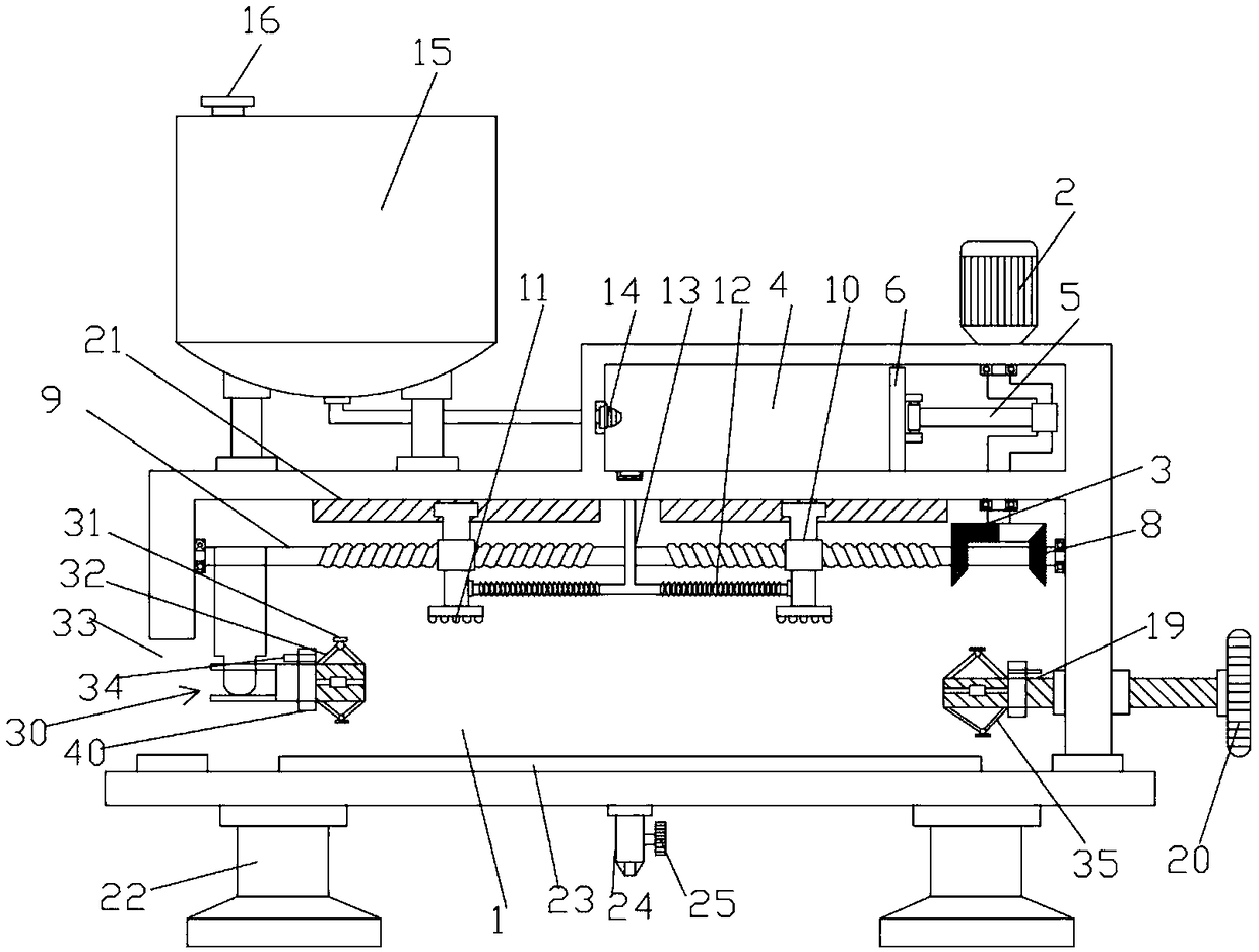
[0047] Such as Figure 1-4 As shown, the pipeline spraying device includes a frame 1, a drive motor 2, a two-way screw mandrel 9, a storage tank 15, an adjustment wheel 20 and a collection tray 23; the upper left side of the frame 1 is fixedly connected to the storage tank 15, The upper end of the material storage tank 15 is provided with a feeding port 16, the upper right side of the frame 1 is provided with a spray chamber 4, and the lower end of the material storage tank 15 is connected to the feeding pipe, and the right end of the feeding pipe is provided with a one-way valve 14, and the one-way valve 14 is connected to the spray chamber 4 The upper part of the spray chamber 4 is fixedly connected to the drive motor 2, the drive motor 2 is electrically connected to the power supply and the switch, the lower end of the drive motor 2 is connected to the upper end of the crankshaft 3 in rotation, the bearing of the crankshaft 3 is connected to the spray chamber 4 in rotation, ...

Embodiment 2

[0051] Such as Figure 5 shown, pipe sprayer, including Rack 1 , a pressurized material storage mechanism located above the frame 1, a feeding mechanism connected to the output end of the storage mechanism, a driving motor 2 located above the feeding mechanism, a transmission mechanism connected to the output end of the driving motor 2, and A paint spraying mechanism connected to the output of the feeding mechanism.

[0052] The above-mentioned feeding mechanism includes a feeding chamber 4 , a feeding piston 6 arranged in the feeding chamber 4 , and an air pressure balance device matched with the feeding piston 6 . A crankshaft 3 is rotatably connected to the downward output end of the above-mentioned drive motor 2, and a connecting rod 5 is rotatably connected between the feed piston 6 and the crankshaft 3. The operation of the drive motor 2 drives the crankshaft 3 to rotate, and the rotation of the crankshaft 3 further drives The connecting rod 5 and the feeding piston 6...

Embodiment 3

[0059] Such as Image 6 with Figure 7 As shown, the pipeline spraying device includes a feeding module, a spraying module and a frame 1 . The upper left side of the above-mentioned frame 1 is fixedly connected to the material storage cylinder 15, the upper end of the material storage cylinder 15 is provided with a feeding port 16 and an air intake hole, the upper right side of the frame 1 is fixedly connected to the air pump 250, and the spray chamber 4 is arranged below the air pump, and the material storage cylinder 15 The lower end communicates with the delivery pipe. The output end of the air pump 250 is connected to the material storage cylinder 15, and the material storage cylinder 15 feeds the spray chamber 4 one-way through the material guide pipe 13 and the one-way valve 14 in sequence. The upper part of the spray chamber 4 is fixedly connected to the driving motor 2, the lower end of the driving motor 2 is connected to the upper end of the bearing 3, and the lower...


PUM


Abstract

The invention discloses a pipeline spraying device comprising a feeding module and a clamping module. The feeding module comprises a machine frame, a spraying cavity formed in the upper portion of themachine frame, a drive motor arranged on the upper portion of the spraying cavity, a two-way lead screw movably connected with the lower portion of the drive motor, spray nozzles connected to the left side and the right side of the two-way lead screw correspondingly, and a liquid guide pipe arranged on the lower portion of the spraying cavity and communicating with each other. The lower portion of the liquid guide pipe is connected with the spray nozzles. The clamping module comprises a universal joint connected to the left side of the two-way lead screw in a rolling manner, a triangle clamping column used for clamping a pipeline and arranged on the universal joint, a regulation wheel arranged on the right side of the machine frame, and a triangle clamping column used for clamping the pipeline and arranged on the regulation wheel. Paint vehicle on the surface of the pipeline is comprehensively sprayed, and the paint vehicle is evenly sprayed.

Description

technical field [0001] The invention belongs to the technical field of pipeline spraying, in particular to a pipeline spraying device. Background technique [0002] At the end of the production process, pipelines often need to be sprayed for anti-corrosion and anti-rust treatment. The existing pipeline painting device has a complex structure and poor painting effect. The paint cannot be evenly sprayed on the surface of the pipeline. Difficult to spray paint. Contents of the invention [0003] In order to overcome the deficiencies of the prior art, the present invention aims to provide a pipeline spraying device with comprehensive and uniform paint spraying. [0004] The second object of the present invention is to provide another pipeline sprayer with high spraying efficiency and uniform spraying. [0005] The third object of the present invention is to provide a third pipeline sprayer with high spraying efficiency and uniform spraying. [0006] In order to realize abov...

Claims


Application Information

Patent Timeline
Patent Type & Authority Applications(China)
IPC IPC(8): B05B9/04B05B13/02B05C1/06
CPCB05B9/0403B05B13/0278B05C1/06
Inventor 朱成林蔡毓旻
Owner 邵勤俏
Why Eureka
Try Eureka