Intelligent direct drive electromagnetic forging hammer
What is Al technical title?
Al technical title is built by PatSnap Al team. It summarizes the technical point description of the patent document.
An electromagnetic and direct drive technology, applied in the direction of forging/pressing/hammer device, forging/pressing/hammering machinery, power hammer, etc., can solve the problems of high equipment maintenance requirements, low energy utilization rate, hard blow, etc., and achieve maintenance Low cost, small mechanical wear, and the effect of reducing mechanical loss
Pending Publication Date: 2018-11-13
郭小红
View PDF0 Cites 1 Cited by
Summary
Abstract
Description
Claims
Application Information
AI Technical Summary
This helps you quickly interpret patents by identifying the three key elements:
Problems solved by technology
Method used
Benefits of technology
Problems solved by technology
Electro-hydraulic hammer is currently widely used forging hammer equipment, but in the process of use, there are also problems such as low energy utilization rate, hard blow, high equipment maintenance requirements, etc. The use of electro-hydraulic hammer is troubled by the above problems
Method used
Image
Click on the blue label to locate the original text in one second.
Reading with bidirectional positioning of images and text.
Examples
Embodiment
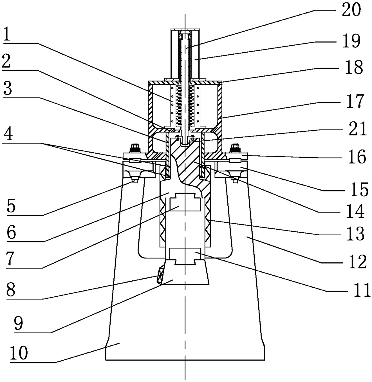
[0035] Such as Figure 1 to Figure 4 As shown, an intelligent direct-drive electromagnetic forging hammer includes a frame, the frame includes a base 10, the upper part of the base 10 is a column 12, the upper part of the column 12 is connected to a frame flange 15, and the frame is connected with a frame flange 15 The upper cross beam 17 is connected to the mover breathing bearing chamber 19 at the upper part of the upper cross beam 17. An upper mold 7 and a lower mold 11 are respectively provided inside the frame, and a cylindrical linear motor 1 is provided in the inner cavity of the upper beam 17.
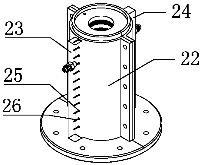
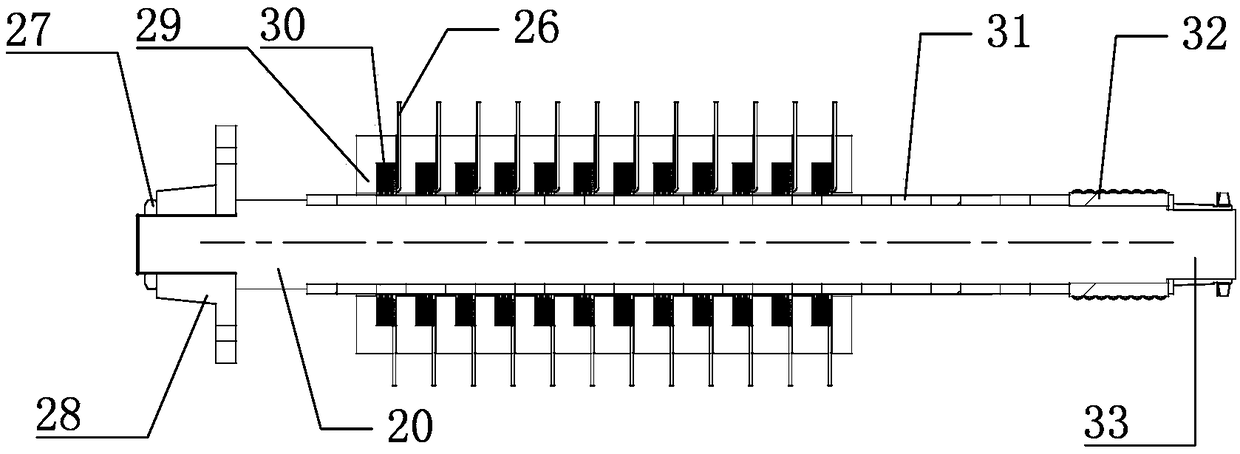
[0036] The upper beam 17 has an inner cavity structure, and the cylindrical linear motor 1 is fixedly installed on the motor mounting surface 2 of the inner cavity of the upper beam 17. The cylindrical linear motor 1 includes a motor housing 22, a cylindrical stator and a cylindrical mover. The stator is installed inside the motor housing 22, the mover is inserted into the stator...
PUM
Property
Measurement
Unit
diameter
aaaaa
aaaaa
Abstract
The invention relates to the technical field of forging, in particular to an intelligent direct drive electromagnetic forging hammer. The intelligent direct drive electromagnetic forging hammer comprises a rack, an upper cross beam is connected to the upper portion of the rack, an upper mold and a lower mold are arranged on the inner side of the rack, a cylindrical linear motor is arranged in an inner cavity of the upper cross beam, and comprises a motor shell, a cylindrical stator, and a cylindrical rotor, the stator comprises multiple stator units connected in sequence, each stator unit comprises an iron core and a coil winding, the iron cores are annular, the coil windings are arranged on the inner sides of the annular shapes, and are connected with a power source, each rotor comprisesa rotor screw, a permanent magnet, a ball sleeve and a set sleeve, the permanent magnets are of annular structures with the inner rings provided with threads, the permanent magnets are arranged on therotor screws, the ball guide sleeves are arranged on the tails of the permanent magnets, and the tails are axially locked through the set sleeves. Thrust is directly generated without any replacing device, in the moving process, no mechanical contact can be achieved, transmission parts are not worn, and mechanical losses are greatly reduced.
Description
Technical field [0001] The invention relates to the technical field of forging, in particular to an intelligent direct-drive electromagnetic forging hammer. Background technique [0002] The forging hammer is a forging machine that uses a transmission mechanism to move the falling part and accumulate kinetic energy, which is applied to the forging in a very short time to obtain plastic deformation energy and complete various forging processes. The falling part includes piston, hammer rod, and hammer head. , Upper anvil or upper module. Forging hammers have always played an important role in the forging industry. [0003] Although the emergence of other forging equipment, such as hydraulic presses and mechanical presses, has replaced part of the work of forging hammers to a certain extent, until now, forging hammers, especially die forging hammers, are still used in the forging industry of various countries. Dominates, most die forgings are produced on hammers. [0004] The air ham...
Claims
Application Information
Patent Timeline
Application Date:The date an application was filed.
Publication Date:The date a patent or application was officially published.
First Publication Date:The earliest publication date of a patent with the same application number.
Issue Date:Publication date of the patent grant document.
PCT Entry Date:The Entry date of PCT National Phase.
Estimated Expiry Date:The statutory expiry date of a patent right according to the Patent Law, and it is the longest term of protection that the patent right can achieve without the termination of the patent right due to other reasons(Term extension factor has been taken into account ).
Invalid Date:Actual expiry date is based on effective date or publication date of legal transaction data of invalid patent.