Pushing and injecting type electric soldering iron

An electric soldering iron and soldering iron technology, applied in the direction of soldering iron, metal processing equipment, welding equipment, etc., can solve problems such as difficult to do, difficult to weld, control, etc., to achieve the effect of easy operation and improved quality

Inactive Publication Date: 2018-11-13
ANHUI UNIV OF SCI & TECH
View PDF5 Cites 2 Cited by
  • Summary
  • Abstract
  • Description
  • Claims
  • Application Information

AI Technical Summary

Problems solved by technology

However, during the use of the soldering iron tip, the working surface is often oxidized due to contact with the pins of the electronic components, and the unadhered solder is heated and oxidized, so that the melted solder cannot adhere to the working surface and cannot be soldered or soldered.
Moreover, it is difficult to control the size, shape and finish of solder joints with traditional adhesion welding

Method used


Image

  • Pushing and injecting type electric soldering iron

Examples


Embodiment Construction

[0014] In order to make the purpose, technical solution and advantages of the application clearer, the application will be described in further detail below in conjunction with the accompanying drawings and specific embodiments. The schematic embodiments and descriptions of the application are used to explain the application, and do not constitute a citation for the application. Improperly qualified.

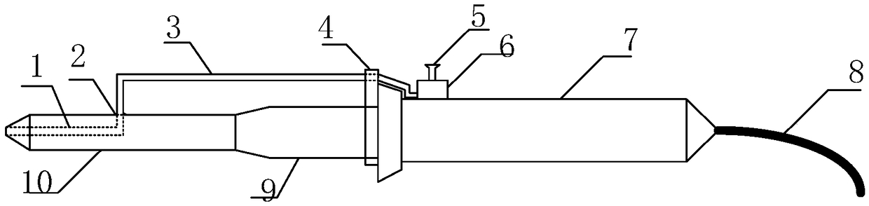
[0015] Such as figure 1 Shown, a kind of injecting electric soldering iron, comprises improved soldering iron head 10, barrier net 2, metal conduit 3, conduit support 4, injector (comprising push rod 5 and injecting chamber 6), soldering iron handle 7, power supply Line 8, heat pipe 9.

[0016] There is a section of cavity 1 inside the improved soldering iron tip 10, which is connected to the outside world by the small hole at the tip of the soldering iron tip 10. The welding wire extends into the cavity from the small hole to melt and is stored in the cavity 1. One end of the ...


PUM


Abstract

The invention relates to a pushing and injecting type electric soldering iron. Compared with a traditional electric soldering iron, the pushing and injecting type electric soldering iron has the characteristics that parts such as an improved soldering iron head, a metal conduit, a pushing and injecting machine and the like are added. A cavity is formed in the improved soldering iron head to storea certain amount of melted solder. One end of the cavity is connected with a small hole at the point end of the soldering iron head, and the other end of the cavity is connected with a metal conduit opening. An obstruction screen is arranged at the connecting position of the metal conduit and the cavity. The metal conduit is fixed by a supporting bracket at a soldering iron handle. One end of themetal conduit is connected with the pushing and injecting machine and the other end of the metal conduit is connected with the cavity of the soldering iron head. When a pushing rod of the pushing andinjecting machine is pressed downwards, the melted solder in the cavity is discharged through the small hole formed in the point end of the soldering iron head. When the pushing rod is loosened, the pushing rod rebounds back and sucks the melted solder back. The pushing and injecting type electric soldering iron overcomes the defects that, according to a traditional electric soldering iron, the melted solder can not attach to the working surface caused by abrasion and oxidation of a soldering iron head,

Description

technical field [0001] The invention relates to the technical field of electric soldering irons, in particular to a push-injection electric soldering iron. technical background [0002] A soldering iron is a widely used soldering tool for electronic components. When a traditional electric soldering iron is in use, a small amount of solder needs to be touched against the working surface of the soldering iron head, so that the solder is heated and melted and adhered to the working surface. However, during the use of the soldering iron tip, the working surface is often oxidized due to contact with the pins of the electronic components, and the unadhered solder is heated and oxidized, so that the melted solder cannot adhere to the working surface and cannot be soldered or soldered. Moreover, it is difficult to control the size, shape, and smoothness of solder joints with traditional adhesion welding. Contents of the invention [0003] In order to solve the above technical pr...

Claims


Application Information

Patent Timeline
Patent Type & Authority Applications(China)
IPC IPC(8): B23K3/03B23K3/06
CPCB23K3/0338B23K3/0607
Inventor 严文俊李良光
Owner ANHUI UNIV OF SCI & TECH
Why Eureka
Try Eureka