
Wiper motor cover plate assembly multi-position assembly machine

A technology of motor cover and plate assembly, which is applied in the direction of electric components, electromechanical devices, electrical components, etc., and can solve the problems of automatic multi-station work assembly, high labor cost, fixing pads and shock-absorbing pads installed on the box cover, etc.

Pending Publication Date: 2018-11-13
GUANGZHOU JIANENG AUTOMATION EQUIP CO LTD
View PDF0 Cites 4 Cited by
  • Summary
  • Abstract
  • Description
  • Claims
  • Application Information

AI Technical Summary

Problems solved by technology

When loading the cover plate assembly of the box cover, it is necessary to install conductive strips, fixing pads, shock absorbing pads, solder and drip irrigation sealant. When installing conductive strips, the existing technology is to manually cut the conductive strips into single conductive strips. The labor cost is high and the work efficiency is low. When installing the fixing pad and the shock absorbing pad, because the fixing pad and the shock absorbing pad are made of hard plastic, it is difficult for the existing machinery and equipment to directly install the fixing pad and the shock absorbing pad on the box cover. superior
In general, for the installation of cover plate components, there is currently no automatic multi-station work assembly machine

Method used


Image

  • Wiper motor cover plate assembly multi-position assembly machine
  • Wiper motor cover plate assembly multi-position assembly machine
  • Wiper motor cover plate assembly multi-position assembly machine

Examples


Embodiment 1

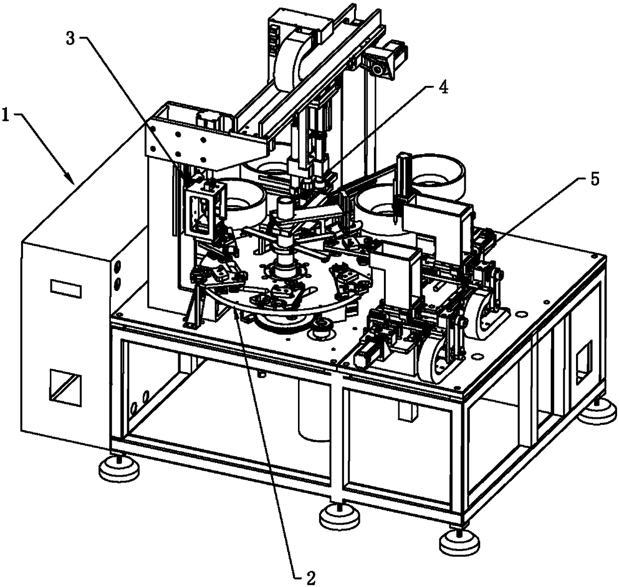
[0043] see figure 1 , the multi-station assembly machine of the wiper motor cover assembly of the present embodiment includes a frame assembly 1, a turntable mechanism 2, a press-cut conductive strip mechanism 3, a rubber pad installation mechanism 4, a soldering and dispensing mechanism 5, and a rubber pad installation The mechanism 4 and the solder and glue dispensing mechanism 5 are arranged outside the turntable 2-1.

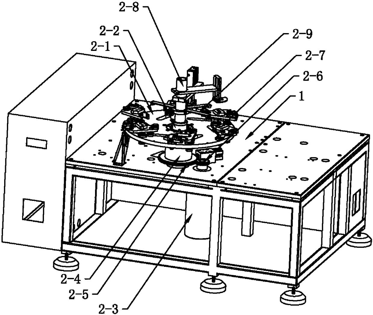
[0044] see figure 1 and figure 2, the turntable mechanism 2 is provided with a turntable 2-1, a central shaft 2-2 and a motor 2-3, the central shaft 2-2 is fixed on the frame assembly 1, the central shaft 2-2 is equipped with a bearing 2-4, and the bearing 2-4 The outer ring of the bearing 2-4 is fixedly connected with the rotating disk 2-1, and the outer ring of the bearing 2-4 is also fixedly connected with a gear plate 2-5, and the gear plate 2-5 meshes with the driving gear 2-6 on the output shaft of the motor 2-3, The turntable 2-1 is provided with ...


PUM


Abstract

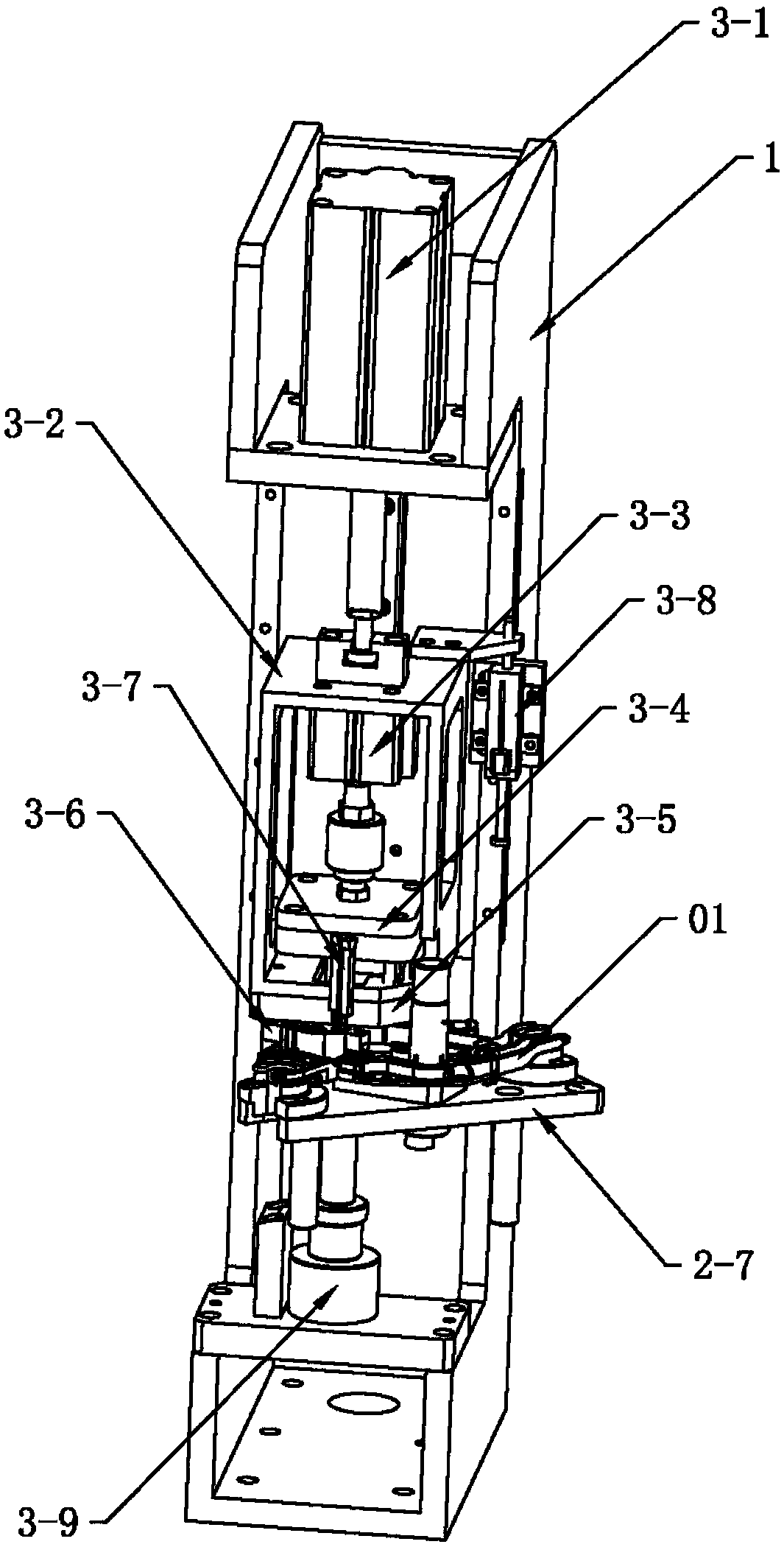
The invention provides a wiper motor cover plate assembly multi-position assembly machine. The wiper motor cover plate assembly multi-position assembly machine comprises a rack assembly, a rotary diskmechanism, a conductive bar press-cutting mechanism, a rubber pad mounting mechanism and a soldering tin and adhesive dispensing mechanism. The rubber pad mounting mechanism and the soldering tin andadhesive dispensing mechanism are arranged on the outer side of a rotary disk. The conductive bar press-cutting mechanism comprises a first cylinder, a sliding seat, a second cylinder, a clamping plate, a pressure head and a cutoff rod. The sliding seat is slidably arranged on the rack assembly through a sliding pair. The first cylinder is fixed to the rack assembly and drives the sliding seat torise and drop. The pressure head is mounted on the lower portion of the sliding seat. The second cylinder is fixed to the sliding seat. The clamping plate is fixed to a telescopic rod of the second cylinder. The cutoff rod is mounted on the clamping plate and penetrates through the pressure head. The first cylinder drives the pressure head to drop in place to press a conductive plate on a workpiece, the cutoff rod is aligned with a connecting section between two adjacent conductive bars, the second cylinder drives the cutoff rod to rush downwards to cut off the connecting section. In this way, the conductive plate on a wiper motor cover plate assembly is automatically cut off without manual cutoff, and the working efficiency is improved.

Description

technical field [0001] The invention relates to the technical field of wiper motor assembly, in particular to the technical field of automatic assembly of a wiper motor cover assembly. Background technique [0002] The wiper motor is one of the main components of the car and is used to clean the glass windows of the car. The wiper motor is driven by the motor, and the rotation of the motor is converted into the reciprocating motion of the wiper arm through the linkage mechanism, so as to realize the wiper action. Generally, the wiper can work when the motor is turned on. By selecting high-speed and low-speed gears, it can change The current of the motor controls the speed of the motor and then the speed of the scraper arm. The main components of the commonly used wiper motor include an armature installed in the casing, the armature is equipped with a worm, the worm is located in the worm box and meshed with the worm gear, the worm gear is connected to the output shaft throu...

Claims


Application Information

Patent Timeline
IPC IPC(8): B23P21/00H02K15/00
CPCH02K15/00B23P21/006B23P2700/50
Inventor 姚牧黄伟峻
Owner GUANGZHOU JIANENG AUTOMATION EQUIP CO LTD
Learn More