Telescopic double-nozzle FDM-3D printer nozzle assembly controlled by electromagnetic

An FDM-3D, nozzle assembly technology, applied in the field of additive manufacturing, can solve the problems of complex internal structure, nozzle influence, increase in the weight of the print head, etc., to reduce control difficulty, reduce weight, and improve printing accuracy and surface accuracy.

Active Publication Date: 2018-11-13
XI AN JIAOTONG UNIV
View PDF3 Cites 7 Cited by
  • Summary
  • Abstract
  • Description
  • Claims
  • Application Information

AI Technical Summary

Problems solved by technology

[0003] Traditional FDM printers have only one nozzle, and can only print one material at a time. With the demand for two-color printing and mixed printing of two materials, FDM printers with dual nozzles have appeared, but the so-called dual nozzles are just two prints. The head components are mechanically connected together, which doubles the weight of the print head, increases the difficulty of control, and has a large vibration, which has a great impact on the printing accuracy; moreover, because the two nozzles are at the same height and cannot be stretched, there is no The working nozzle will affect the printed part during the movement, resulting in a decrease in surface quality
[0004] Patent CN108115935A proposes a single-motor double-nozzle FDM printer extrusion mechanism, but its internal structure is complex, the weight reduction effect is limited, the purpose of weight reduction is not really achieved, and it does not solve the problem that the non-working nozzles will affect during the movement process. Problems such as printed parts; patent CN207432783U proposes a double-nozzle FDM printer extrusion mechanism, which intends to solve the problems of insufficient distance accuracy between the two print heads and the difficulty of the same height between the two print heads, but does not reduce the weight of the dual-nozzle printer nozzle assembly. It also does not solve the problem that the non-working nozzle will affect the printed part during the movement

Method used


Image

  • Telescopic double-nozzle FDM-3D printer nozzle assembly controlled by electromagnetic

Examples


Embodiment Construction

[0031] The present invention is described in further detail below in conjunction with accompanying drawing:

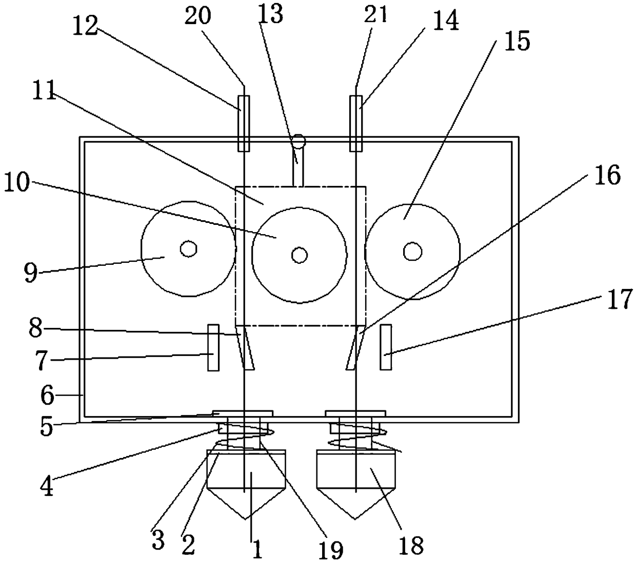
[0032] Such as figure 1 As shown, the spray head assembly of the present invention includes a fixed frame 6 , a motor 11 and a driving wheel 10 .

[0033] The first driven wheel 9 and the second driven wheel 15 are respectively symmetrically arranged on both sides of the driving wheel 10, and the end faces of the three are in the same plane. Connected so that the driving wheel 10 and the motor 11 can swing towards both sides.

[0034] Both sides of the bottom of the motor 11 are respectively symmetrically fixed with a second iron sheet 8 and a third iron sheet 16, and the outer sides of the second iron sheet 8 and the third iron sheet 16 are respectively symmetrically provided with a second electromagnet 7 and a second electromagnet fixed on the fixed frame 6. Three electromagnets 17.

[0035] The fixing frame 6 is respectively provided with a first material guide t...


PUM


Abstract

The invention provides a telescopic double-nozzle FDM-3D printer nozzle assembly controlled by electromagnetic. The assembly comprises a fixing frame, a motor and a driving wheel; when a first nozzleworks, the motor rotates, a second electromagnet is electrified, and a third iron sheet is attracted to tight compress the driving wheel and a second driven wheel to convey a first wire rod; and whena second nozzle works, the motor is rotated reversely, a third electromagnet is electrified, and the third iron sheet is attracted to tight compress the driving wheel and the second driven wheel to convey a second wire rod. The motor is driven to swing towards the two sides, the driving wheel is driven to cooperate with the two driven wheels on the two sides correspondingly, so that the two wire rods can be extruded out, and the two nozzles can be fed; and on the premise that the basic function of a nozzle assembly is guaranteed, the weight of one motor and the weight of one friction wheel arereduced greatly, so that the control difficulty is reduced, and the printing precision and the surface precision are improved.

Description

technical field [0001] The invention belongs to the field of additive manufacturing, and relates to an electromagnetically controlled scalable dual-nozzle FDM-3D printer nozzle assembly. Background technique [0002] The Fused Deposition Rapid Prototyping (FDM) process is by extruding a filamentous material such as a thermoplastic, wax or metal fuse from a heated nozzle, and performing melt deposition at a fixed rate according to a predetermined trajectory for each layer of the part, Every time a layer is completed, the workbench is lowered by one layer thickness to superimpose and deposit a new layer, so that the deposition and molding of the parts are finally realized through repetition. The biggest difference between the FDM system and other 3D printing systems is that FDM does not use a laser system, which reduces the maintenance cost to the lowest level. In addition, it has simple equipment, clean process, low operating cost and no garbage, and can quickly build hollow ...

Claims


Application Information

Patent Timeline
Patent Type & Authority Applications(China)
IPC IPC(8): B29C64/112B29C64/118B29C64/209B29C64/30B33Y30/00
CPCB29C64/112B29C64/118B29C64/209B29C64/30B33Y30/00
Inventor 梁庆宣周文卿
Owner XI AN JIAOTONG UNIV
Why Eureka
Try Eureka