Hybrid electric vehicle transmission device

A hybrid electric vehicle and transmission technology, applied in hybrid electric vehicles, power devices, air pressure power devices, etc., can solve the problem of unreasonable axial and radial space layout, complex hydraulic system oil channel layout, and low engine operating efficiency and other problems to achieve the effect of simplifying the layout of the oil passage, improving the production process and assembly process, and reducing the torque performance requirements

Pending Publication Date: 2018-11-13
无锡明恒混合动力技术有限公司
View PDF0 Cites 12 Cited by
  • Summary
  • Abstract
  • Description
  • Claims
  • Application Information

AI Technical Summary

Problems solved by technology

[0004] However, the transmission device of the existing hybrid electric vehicle, especially the longitudinal rear-drive model, often due to the low degree of integration, will lead to the occurrence of slender shafts due to the mutual nesting of multiple shafts, and will also cause axial and radial space. Unreasonable layout
In addition, due to the limitation of the transmission device of the existing hybrid electric vehicles, the layout of the hydraulic system and the oil passage is relatively complicated.
Moreover, the transmission device of the prior art causes the operating efficiency of the engine to be low, and the situation of low efficiency and high emission occurs
[0005] There are at least the following problems in the prior art: the transmission device of the existing hybrid electric vehicle, especially the longitudinal rear-drive model, often due to the low degree of integration, will cause the situation of slender shafts due to the mutual nesting of multiple shafts, and also It will lead to unreasonable axial and radial space layout
In addition, due to the limitation of the transmission device of the existing hybrid electric vehicles, the layout of the hydraulic system and the oil passage is relatively complicated.
Moreover, the transmission device of the prior art causes the operating efficiency of the engine to be low, and the situation of low efficiency and high emission occurs

Method used


Image

  • Hybrid electric vehicle transmission device

Examples


Embodiment Construction

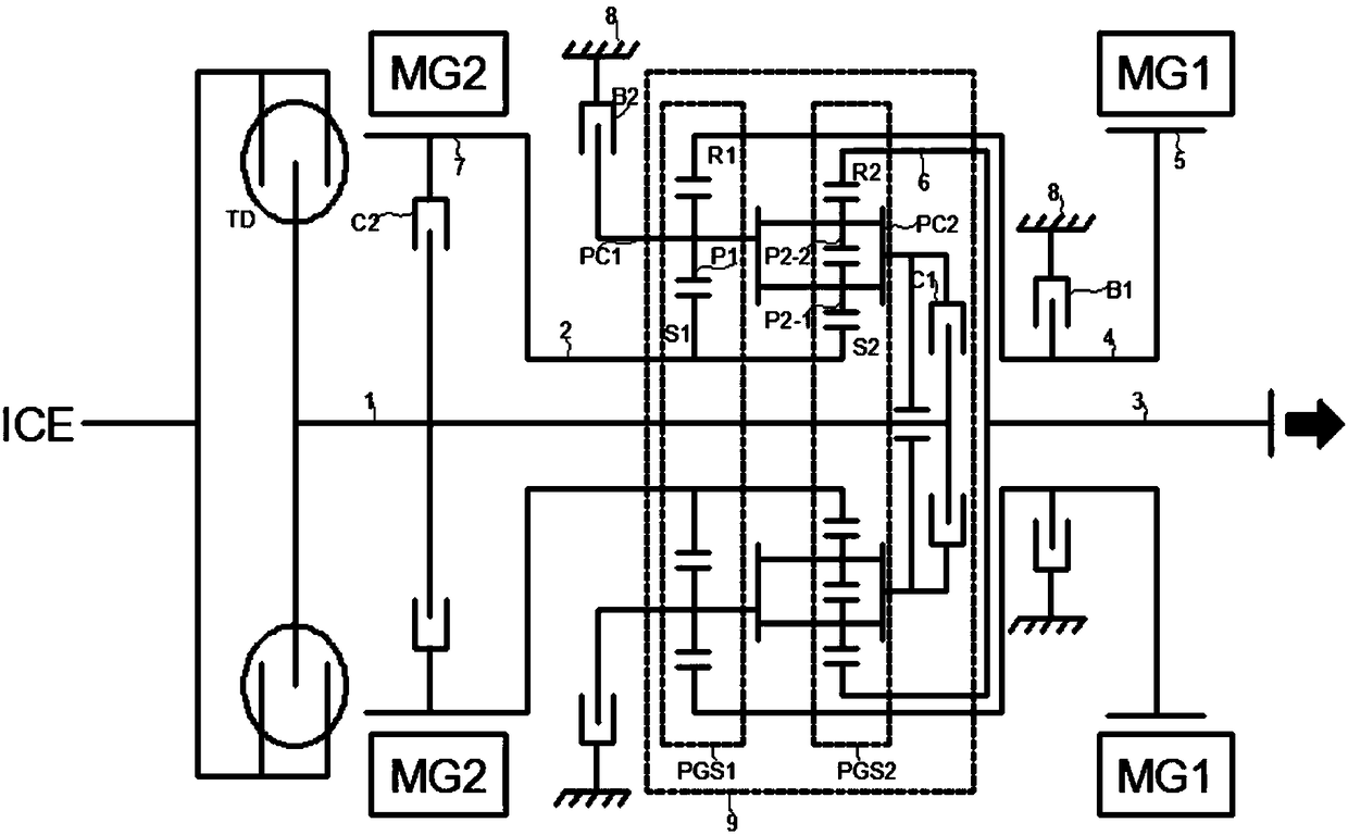
[0018] The preferred embodiment of the present invention will be described in detail below in conjunction with accompanying drawing:

[0019] figure 1 It is a device structure schematic diagram of a transmission device of a hybrid electric vehicle provided by an embodiment of the present application. A device structure diagram of an embodiment. Although the present application provides the device structure as shown in the following embodiments or drawings, more or less modular units may be included in the device based on routine or no creative effort. In structures where logically there is no necessary causal relationship, the modular structures of these devices are not limited to the exemplary embodiments of the present application or the modular structures shown in the accompanying drawings.

[0020] Specifically, such as figure 1 As stated, an embodiment of a transmission device for a hybrid electric vehicle provided by the present application may include:

[0021] Inpu...


PUM


Abstract

The invention relates to a hybrid electric vehicle transmission device. The hybrid electric vehicle transmission device comprises a planetary gear coupling mechanism, wherein the planetary gear coupling mechanism comprises a single-planetary row and a double-planetary row, the single-planetary row comprises a first sun wheel, a first planet gear, a first planet carrier and a first gear ring, and the double-planetary row comprises a second sun wheel, an inner planet wheel, an outer planet wheel, a second planet carrier and a second gear ring. An input shaft is used as the first transmission shaft, the two sun wheels are connected with each other and then connected with a rotor shaft of a second motor, and a second transmission shaft is constituted. The two planet carriers are connected to constitute a third transmission shaft, the first gear ring is connected with a rotor shaft of a first motor to constitute a fourth transmission shaft, and the second gear ring constitute an output shaft. The input shaft is connected to the output end of an engine through a torsional shock absorber. The first motor is connected to one end of a first brake, and a transmission housing is connected tothe other end of the first brake. The second motor is connected to one end of a second brake, and the transmission housing is connected to the other end of the second brake. By using the embodiments of the hybrid electric vehicle transmission device, the device structure can be optimized, and the transmission efficiency is improved.

Description

technical field [0001] The invention relates to the technical field of hybrid electric vehicles, in particular to a hybrid electric vehicle transmission device. Background technique [0002] With the rapid development of science and technology, China's demand for traditional energy such as oil is increasing year by year. However, due to production capacity factors such as oil wells and oil fields, my country's crude oil storage has been greatly reduced, and the sharp rise in oil prices has affected gasoline and diesel. price. Exhaust emissions from traditional fuel vehicles contain carbon monoxide, hydrocarbons and other harmful substances that are harmful to the environment and the human body. Vehicle exhaust emissions have become one of the main sources of urban air pollution. [0003] With the continuous adjustment of policies on automobile emissions and new energy vehicles in various countries around the world, my country will begin to implement the National VI emission ...

Claims


Application Information

Patent Timeline
Patent Type & Authority Applications(China)
IPC IPC(8): B60K6/365B60K6/26B60K6/38B60K6/24
CPCB60K6/24B60K6/26B60K6/365B60K6/38Y02T10/62
Inventor 陈旭灿洪波昌张彤张峻支峰何正模唐师法魏军
Owner 无锡明恒混合动力技术有限公司
Why Eureka
Try Eureka