
Supporting part of reinforcement cage and application method thereof

A technology for supporting parts and reinforcing cages, which is applied in construction, infrastructure engineering, sheet pile walls, etc., can solve the problems of non-reusable cross braces, loose cross braces, and deformation of reinforcing cages, saving engineering materials and The construction period, the effect of improving the overall strength and reducing the difficulty

Pending Publication Date: 2018-11-13
CHINA RAILWAY NO 2 ENG GRP CO LTD +1
View PDF5 Cites 0 Cited by
  • Summary
  • Abstract
  • Description
  • Claims
  • Application Information

AI Technical Summary

Problems solved by technology

[0002] In the construction process of the pile foundation reinforcement cage, the existing technology usually uses cross bracing directly welded on the inside of the reinforcement cage, so as to support the reinforcement cage skeleton during hoisting and transportation, so that the reinforcement cage skeleton does not deform, and when the concrete is poured, the conduit will Occupies the position of the cross brace, so when the steel cage is lowered into the cage, the cross brace must be removed one by one, the workload is heavy, the operation is cumbersome, time-consuming, and the efficiency is low, and the cross brace reinforcement cannot be reused, resulting in waste of materials
At the same time, the steel cage is supported by cross braces, which is prone to poor welding, which will cause the cross braces to loosen and fall, resulting in deformation of the steel cage and other problems.

Method used


Image

  • Supporting part of reinforcement cage and application method thereof
  • Supporting part of reinforcement cage and application method thereof
  • Supporting part of reinforcement cage and application method thereof

Examples


Embodiment 1

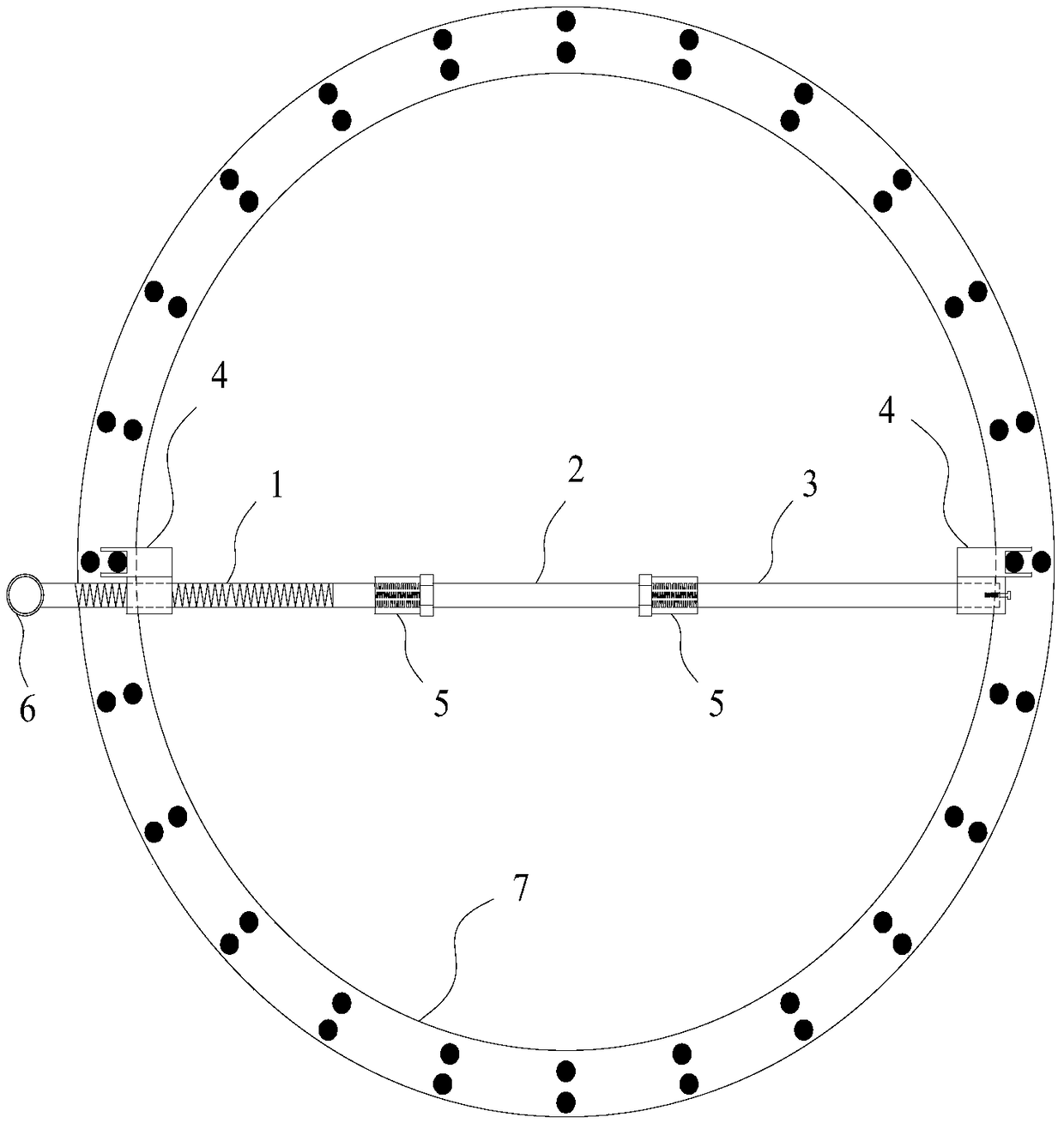
[0037] A support part of a reinforcement cage according to the present invention, such as Figure 1-2 As shown, it includes a rod one 1, a connecting part 2 and a rod two 3, and the connecting part 2 includes a straight rod, and the rod one 1 and the rod two 3 are respectively connected to the two ends of the straight rod, Preferably, the first rod 1 and the second rod 3 are detachably connected to both ends of the in-line rod, and further preferably, the rod one 1 and the second rod 3 are respectively screwed to the in-line rod The two ends of the piece, preferably, the rod one 1 is a screw rod, the slot 4 on the rod one 1 is threadedly connected to the screw rod, the end of the screw rod is connected with a torque cylinder 6, and the rod two 3 The said draw-in slot 4 is fixedly connected to the end of said rod 3, and said rod one 1 and rod two 3 are all provided with fastening nuts 5 at the joints of said rod one and rod two 3, and said rod one 1 Collinear with bar two 3, e...

Embodiment 2

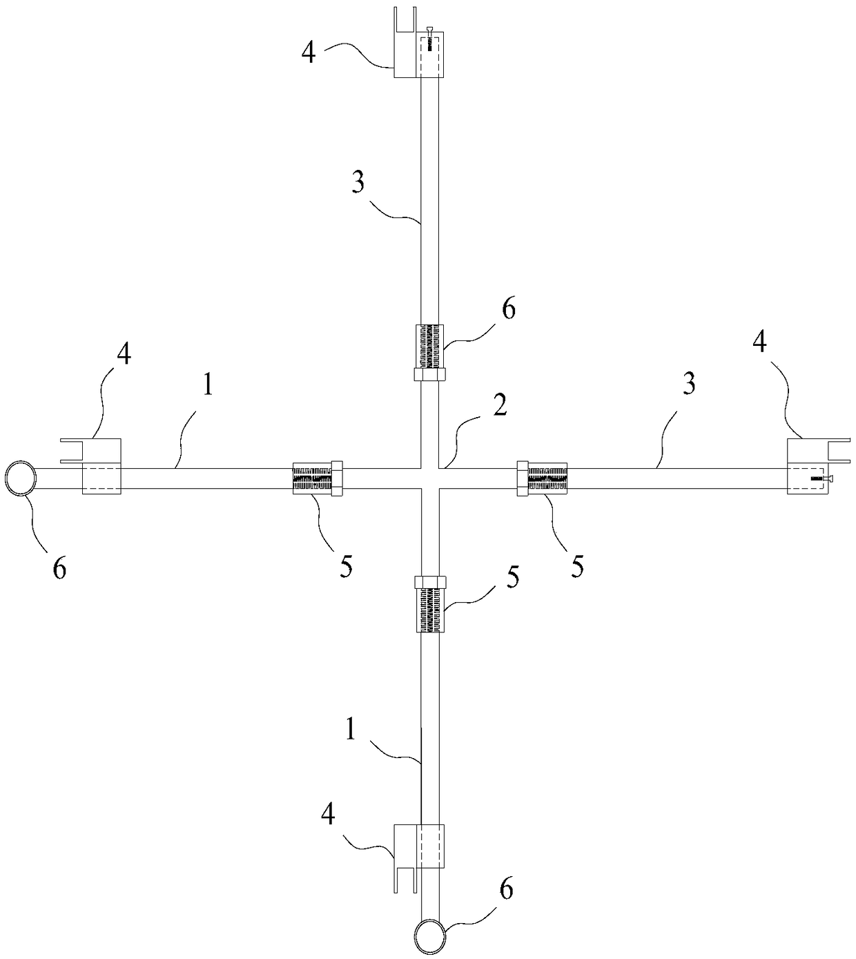
[0040] A support part of a reinforcement cage according to the present invention, such as image 3 As shown, its structure is roughly the same as that of Embodiment 1, the difference is that the connecting part 2 includes two in-line rods, and each of the two ends of the in-line rods is respectively connected to one of the rods One 1 and one rod two 3, the two said in-line rods are integrally formed structural parts perpendicular to each other, the two rods one 1 are all polished rods, and the clips arranged on the rod one 1 The slot 4 is slidingly connected to the rod one 1 through a sleeve, and the sleeve is provided with a locking bolt.

[0041] During use, earlier the draw-in groove 4 on the described bar two 3 of two described inline rods blocks the inboard of reinforcement cage 7, slides the draw-in groove 4 on two bar one 1 respectively then and blocks corresponding described The inner side of the reinforcement cage 7 opposite to the rod 2 3 can be fastened without loo...

Embodiment 3

[0043] The using method of the support member of a kind of reinforcement cage of the present invention adopts the support member of any one reinforcement cage as in embodiment 1-2, and its use method comprises the following steps:

[0044] a. First use a card slot 4 on the straight rod to block the inner side of the reinforcement cage 7;

[0045] b. Adjust the distance between the two slots 4 on the same straight bar, so that the other slot 4 clamps the inner side of the other side of the reinforcement cage 7;

[0046] c. Connect the supporting part with the reinforcement cage 7 with a rope to complete the installation of the supporting part.

[0047]Using this method, according to the diameter of the steel cage 7 to be supported, select the connecting part 2 of suitable length, then clamp the slot 4 of the rod 23 on the inside of the steel cage 7, and then rotate the torque cylinder 6 or slide the slot 4 to make The draw-in groove 4 on the bar one 1 blocks the other side of ...


PUM


Abstract

The invention discloses a supporting part of a reinforcement cage and an application method thereof. The supporting part comprises a bar I, a connecting part and a bar II. The connecting part comprises a "-"-shaped bar part, the bar I and the bar II are separately connected to two ends of the "-"-shaped bar part, the bar I and the bar II are collinear, slots are connected to the bar I and the barII, separately, the notches of the two slots are formed in directions, far away from the connecting part, and the pitch between the two slots is adjustable. By adopting the device, the reinforcement cage can be supported effectively, the integral strength of the reinforcement cage is improved, deformation of the reinforcement cage in hoisting and conveying processes is avoided, the quality of thereinforcement cage is guaranteed, and the hole forming quality of a pile foundation is improved. The supporting part is convenient to detach and mount and can be repeatedly used, so that the safety ofthe hoisting process is improved. Meanwhile, damage caused by welding and cutting operations and welding and cutting on the reinforcement cage is avoided, the use level of supporting reinforcing steel bars is saved greatly, and the mounting and detaching work efficiency is improved.

Description

technical field [0001] The invention relates to the technical field of pile foundation reinforcement cage construction, in particular to a support component of a reinforcement cage and a use method thereof. Background technique [0002] In the construction process of the pile foundation reinforcement cage, the existing technology usually uses cross bracing directly welded on the inside of the reinforcement cage, so as to support the reinforcement cage skeleton during hoisting and transportation, so that the reinforcement cage skeleton does not deform, and when the concrete is poured, the conduit will Occupying the position of the cross bracing, so when the steel cage is lowered, the cross bracing must be removed one by one, the workload is heavy, the operation is cumbersome, it takes a long time, the efficiency is low, and the cross bracing reinforcement cannot be reused, resulting in waste of materials. At the same time, the cross bracing of the steel cage is prone to poor ...

Claims


Application Information

Patent Timeline
Patent Type & Authority Applications(China)
IPC IPC(8): E02D5/34
CPCE02D5/34
Inventor 刘洋杨小东赵伟
Owner CHINA RAILWAY NO 2 ENG GRP CO LTD
Learn More