
Sealing structure and sealing method of plastic template

A technology of plastic formwork and sealing structure, applied in the field of sealing device of building formwork, can solve problems such as chromatic aberration, and achieve the effects of convenient construction and use, easy cleaning, and reduction of water loss

Inactive Publication Date: 2018-11-13
河北润林新材料科技有限公司
View PDF0 Cites 2 Cited by
  • Summary
  • Abstract
  • Description
  • Claims
  • Application Information

AI Technical Summary

Problems solved by technology

[0005] One of the purposes of the present invention is to provide a sealing structure for plastic formwork to solve the problem that the existing plastic formwork is seriously screened in the formwork gap during the vibration process and easily causes color difference at the seam

Method used


Image

  • Sealing structure and sealing method of plastic template

Examples


Embodiment 1

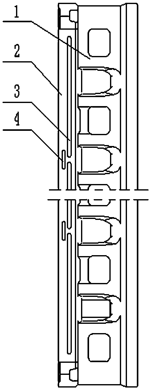
[0026] Embodiment 1, a sealing structure of a plastic template.

[0027] like figure 1 As shown, the plastic template includes a panel and a frame 1 arranged around the back of the panel. The frame 1 has two opposite side edges, and one side edge 2 is close to the panel.

[0028] On the side edge 2 of the frame 1 next to the panel, there are several elongated long U-shaped grooves 3 with a U-shaped cross section. The length direction of these long U-shaped grooves 3 is along the side edge 2 of the frame 1, and The long U-shaped grooves 3 are parallel to the bottom of the frame 1, and the long U-shaped grooves 3 form a discontinuous intermittent arrangement. The length of the long U-shaped groove 3 is generally set at 50 mm to 100 mm. When the concrete is poured later, under the action of the vertical vibrating force, the moisture flowing into the long U-shaped groove 3 can be retained in the groove. If the length of the long U-shaped groove 3 is set too long, the water will...

Embodiment 2

[0033] Embodiment 2, a sealing method of a plastic template.

[0034] combine figure 1 , the sealing method of plastic formwork provided by the present invention, comprises the steps:

[0035] a. On the side edge 2 of the frame 1 close to the panel of the plastic formwork, open several long U-shaped grooves 3 with a U-shaped cross-section, and connect two adjacent long grooves 3 on the side edge 2 of the frame 1 close to the panel. The discontinuous parts between the U-shaped grooves 3 are opposite to each other, and a long U-shaped short U-shaped groove 4 with a U-shaped cross section is set up. The length of the short U-shaped groove 4 is greater than the discontinuity between the two long U-shaped grooves 3 opposite to it. The length of the position, the short U-shaped groove 4 is far away from the distance of the plastic formwork panel, and the distance of the U-shaped groove 3 is far away from the plastic formwork panel.

[0036] For the relevant introduction of the lon...


PUM

PropertyMeasurementUnit
Lengthaaaaaaaaaa

Abstract

The invention provides a sealing structure and a sealing method of a plastic template. According to the sealing structure of the plastic template, a plurality of U-shaped grooves with a certain lengthare formed in the side edge, close to a panel, of a frame of the plastic template, and a plurality of short U-shaped grooves are formed on the side edge, corresponding to the discontinuous positionsbetween the adjacent two long U-shaped grooves, of the frame; so that after plastic templates are assembled and butted, the long U-shaped grooves on the side edges of frames of the adjacent two plastic templates are fitted up correspondingly to form a sealing cavity, and meanwhile the short U-shaped grooves are also fitted up correspondingly to form another sealing cavity. When concrete is pouredlater, water flows into the sealing cavities from a template gap under own pressure of the concrete and a vibrating action, the water filling the sealing cavities forms a weir plug effect, and thus the water flowing out of the template gap at a high speed is slowed down and delayed, and the speed of water loss is reduced. Floating slurry flowing into the sealing cavities can also play a role in blocking water, and the disadvantage of rapid water screening effect caused by hydrophobic plastic is overcome and a sealing role is achieved under a dual role of the above situation.

Description

technical field [0001] The invention relates to a sealing device of a building formwork, in particular to a sealing structure of a plastic formwork and a sealing method thereof. Background technique [0002] Building formwork is a necessary construction tool in the construction of modern pouring concrete structures. Traditional building formwork mainly includes wood formwork and steel formwork. The use of wooden formwork, on the one hand, consumes a lot of wood, which is not conducive to environmental protection; on the other hand, its reusability is low. Steel formwork is difficult to manufacture and process, and the cost of use is high; and it is heavy, which is not conducive to transportation and installation. Now the traditional wood formwork and steel formwork are gradually replaced by plastic formwork. Plastic templates are being used more and more widely because of their light weight, simple processing technology, and high degree of reusability. [0003] During on...

Claims


Application Information

Patent Timeline
IPC IPC(8): E04G9/05
CPCE04G9/05Y02E10/20
Inventor 曹海峰张灵巧
Owner 河北润林新材料科技有限公司
Learn More