
Building energy efficiency system using multiple renewable energy sources

A renewable energy and building energy-saving technology, applied in the direction of renewable energy integration, sustainable buildings, buildings, etc., can solve the problems that the power grid is easy to damage the ecological environment, unfavorable for tourists to enjoy the scenery, and difficult to attract tourists. The effect of small area, convenient construction and beautiful appearance

Inactive Publication Date: 2018-11-13
TIANJIN UNIV
View PDF0 Cites 2 Cited by
  • Summary
  • Abstract
  • Description
  • Claims
  • Application Information

AI Technical Summary

Problems solved by technology

The more commonly used renewable energy is solar energy, wind energy, etc. At present, it is difficult for most buildings to use multiple renewable energy sources for their own use at the same time, especially the construction of tourist resort buildings in scenic spots requires the laying of power grids for power supply, and the laying of power grids is easy to damage The beauty of the original ecological environment, the current scenic spot buildings are fixed construction, the shape is not individual enough and the viewing angle is fixed, which is not conducive to tourists' appreciation of the all-round scenery, and it is difficult to attract tourists

Method used


Image

  • Building energy efficiency system using multiple renewable energy sources
  • Building energy efficiency system using multiple renewable energy sources
  • Building energy efficiency system using multiple renewable energy sources

Examples


Embodiment Construction

[0013] In order to make the purpose, technical solutions and advantages of the embodiments of the present invention clearer, the technical solutions in the embodiments of the present invention will be clearly and completely described below in conjunction with the drawings in the embodiments of the present invention. Obviously, the described embodiments It is a part of embodiments of the present invention, but not all embodiments. Based on the embodiments of the present invention, all other embodiments obtained by persons of ordinary skill in the art without creative efforts fall within the protection scope of the present invention.

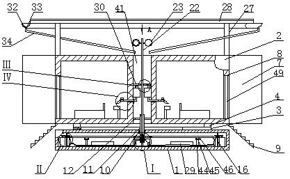
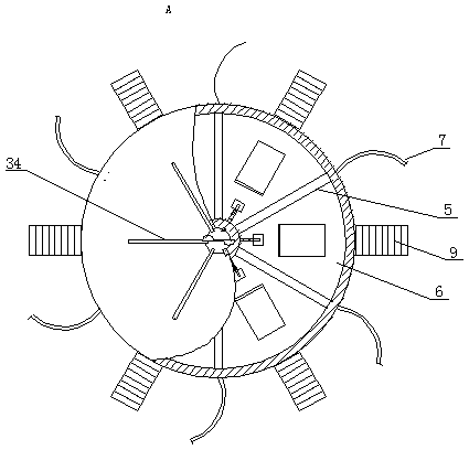
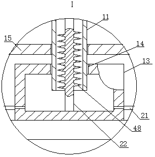
[0014]A building energy-saving system using multiple renewable energy sources, as shown in the figure, includes a circular base 1, the base 1 is hollow inside, and the upper part of the base 1 is provided with an annular square tubular room 2, and the center of the room 2 and the base 1 The lines are coaxial, and the upper part of the base 1 is fi...


PUM


Abstract

The invention provides a building energy efficiency system using multiple renewable energy sources. The building energy efficiency system includes a circular base, and the interior of the base is hollow. A house body in an annular square pipe shape is arranged on the upper portion of the base, the house body and the center line of the base are coaxial, and an annular rail is fixedly arranged on the upper portion of the base. Multiple uniformly distributed sliding blocks are arranged between the annular rail and the house body in a matched mode. Multiple uniformly distributed division plate walls are fixedly arranged in the house body, and the multiple division plate walls divide the house body into multiple fan-shaped rooms. Curved plates are fixedly installed at the position, corresponding to the outer end of the division plate walls, of outer circumference of the house body. Doors are arranged at the position, corresponding to the rooms, of the outer circumference of the house body.Ladders are fixedly installed at the position, corresponding to the doors, of the bottom of the outer circumference of the house body. A first through hole is formed in the middle of the top surface of the base. The building energy efficiency system is suitable for installation on the scenic area of beautiful and windy mountain tops or seaside for tourists to live in and use, can use wind energy,solar energy and other renewable energy sources to generate electricity and store, supply the whole building energy efficiency system to use, and save energy.

Description

technical field [0001] The invention belongs to the technical field of energy-saving buildings, in particular to a building energy-saving system utilizing multiple renewable energy sources. Background technique [0002] Renewable energy includes solar energy, water energy, wind energy, biomass energy, wave energy, tidal energy, ocean temperature difference energy, geothermal energy, etc. They can be recycled in nature. It is an inexhaustible and inexhaustible energy, which will be automatically regenerated without human participation. It is a kind of energy relative to non-renewable energy that will be exhausted. The more commonly used renewable energy is solar energy, wind energy, etc. At present, it is difficult for most buildings to use multiple renewable energy sources for their own use at the same time. In particular, the construction of tourist resort buildings in scenic spots also requires the laying of power grids for power supply. The laying of power grids is easil...

Claims


Application Information

Patent Timeline
Patent Type & Authority Applications(China)
IPC IPC(8): F03D9/25F03D9/11F03D9/45E04B1/346E04H3/02E03B3/02E04H1/12H02S10/12H02J7/35
CPCE03B3/02E04B1/346E04H1/1205E04H3/02F03D9/007F03D9/11F03D9/25F03D9/45H02J7/35H02S10/12Y02B10/10Y02B10/30Y02E10/50Y02E10/72Y02E10/728Y02E10/76Y02E70/30Y02A20/108
Inventor 朱能刘祥哲董琦崔力丹崔梓萌吕明岳
Owner TIANJIN UNIV
Learn More