Safe silicon nitride igniter

A silicon nitride point and safety-type technology, which is applied in the direction of combustion ignition, incandescent ignition, combustion methods, etc., can solve problems such as splashing and falling, damage to external wires, and inability to fix fragments, so as to avoid mutual entanglement, improve safety, The effect of simple structure

Pending Publication Date: 2018-11-13
中能华邦环保科技有限公司
View PDF6 Cites 0 Cited by
  • Summary
  • Abstract
  • Description
  • Claims
  • Application Information

AI Technical Summary

Problems solved by technology

[0002] The excellent performance of silicon nitride igniter is suitable for the working environment of high temperature, high speed and strong corrosive medium often encountered by modern technology, but with the development of science and technology, people have higher and higher requirements for silicon nitride igniter, resulting in the traditional The existing silicon nitride igniter can no longer meet people's needs, and people need a safer and more convenient silicon nitride igniter; the existing silicon nitride igniter has certain disadvantages in use, first of all, it cannot be well isolated Heat, when used for a long time, the wire inside the insulating ceramic is easy to be damaged by heat. Secondly, when the silicon nitride ceramic heating element is damaged by force, the fragments cannot be fixed well, and the damage will splash and fall easily. It affects the normal use of other equipment. Finally, when the existing silicon nitride igniter is installed and used, the silicon nitride igniter needs to be fixed, and the external wire is easy to be entangled. At the same time, the external wire is easily damaged by external influences. Timely replacement will bring a certain impact. Therefore, we propose a safe silicon nitride igniter

Method used


Image

  • Safe silicon nitride igniter
  • Safe silicon nitride igniter
  • Safe silicon nitride igniter

Examples


Embodiment Construction

[0017] In order to make the technical means, creative features, goals and effects achieved by the present invention easy to understand, the present invention will be further described below in conjunction with specific embodiments.

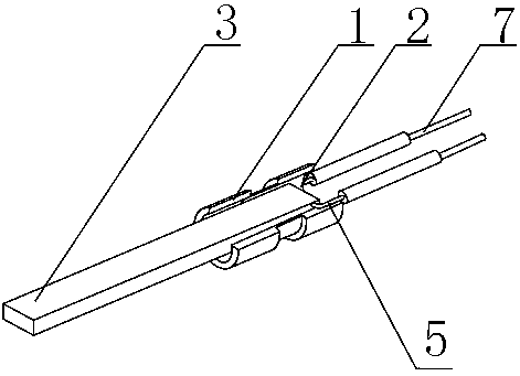
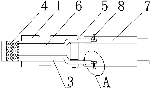
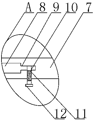
[0018] Such as Figure 1-4 As shown, a safety type silicon nitride igniter includes an insulating ceramic 1, a placement groove 2 is opened through the inner center of the insulating ceramic 1, and a silicon nitride ceramic heating element 3 is inlaid inside the placement groove 2. The silicon ceramic heating element 3 is provided with a porous ceramic plate 4 near the insulating ceramic 1, and the silicon nitride ceramic heating element 3 is provided with inner wires 5 on both sides of the outer surface near the rear end. The inside of 3 is provided with a heating wire 6 near the position of the inner wire 5, the rear end of the inner wire 5 is provided with an outer wire 7, and one end of the inner wire 5 is provided with a connecting wire 8, an...


PUM


Abstract

The invention discloses a safe silicon nitride igniter. The safe silicon nitride igniter comprises an insulating ceramic, a storing groove is formed in the internal center of the insulating ceramic ina penetrating mode, and a silicon nitride ceramic heating element is embedded in the storing groove. According to the safe silicon nitride igniter, a porous ceramic plate, a copper wire net and an energizing pin are arranged, the heat can be isolated well, the temperature is prevented from being transferred into the insulating ceramic, the temperature is concentrated on the insulating ceramic, the normal work of the internal wires is affected, and the safety can be improved better; and when the silicon nitride ceramic heating element breaks, the copper wire net can play a temporary connectionrole, and the normal use of other equipment is affected due to the splashing during the fragmentation of the silicon nitride ceramic heating element is avoided; and the later use is affected due to the entangling of the outer wires during installation can be further avoided well, meanwhile, the damaged outer wires can be replaced more conveniently, and the better use prospects are brought.

Description

technical field [0001] The invention relates to the field of igniters, in particular to a safe silicon nitride igniter. Background technique [0002] The excellent performance of silicon nitride igniter is suitable for the working environment of high temperature, high speed and strong corrosive medium often encountered by modern technology, but with the development of science and technology, people have higher and higher requirements for silicon nitride igniter, resulting in the traditional The existing silicon nitride igniter can no longer meet people's needs, and people need a safer and more convenient silicon nitride igniter; the existing silicon nitride igniter has certain disadvantages in use, first of all, it cannot be well isolated Heat, when used for a long time, the wire inside the insulating ceramic is easy to be damaged by heat. Secondly, when the silicon nitride ceramic heating element is damaged by force, the fragments cannot be fixed well, and the damage will s...

Claims


Application Information

Patent Timeline
Patent Type & Authority Applications(China)
IPC IPC(8): F23Q7/00F23Q7/24F23Q7/22
CPCF23Q7/00F23Q7/22F23Q7/24
Inventor 南丁天王付华王鼎王爱华杨彤
Owner 中能华邦环保科技有限公司
Why Eureka
Try Eureka