Magnetic resonance effect based imprinting sensor

A sensor and effect technology, applied in the field of magnetic resonance effect imprinting sensors, can solve the problems of simple function, single detection method, and inability to provide imprint measurement functions, etc., to improve measurement accuracy, overcome non-specificity, strong versatility and portability Effect

Inactive Publication Date: 2018-11-13
TAIYUAN UNIV OF TECH
View PDF6 Cites 0 Cited by
  • Summary
  • Abstract
  • Description
  • Claims
  • Application Information

AI Technical Summary

Problems solved by technology

[0004] The main principle of molecular imprinting technology is to combine functional monomers and template molecules with cross-linking agents or electropolymerization through special forces to prepare molecularly imprinted polymers, and then remove the residual template molecules by eluting with certain solvents or other methods. The size, shape, and spatial configuration of the template molecule are complementary to the hole, so that it has the ability to specifically recognize the template molecule; the imprinted sensor made by imprinting technology has the characteristics of small size and portability, but the imprinted sensor currently used The sensor is limited by the type and quality of the hardware, and cannot provide real-time and accurate imprint measurement functions. The detection method is single and the function is simple, which greatly restricts the application of imprint sensing technology and needs to be improved.

Method used


Image

  • Magnetic resonance effect based imprinting sensor
  • Magnetic resonance effect based imprinting sensor
  • Magnetic resonance effect based imprinting sensor

Examples


Embodiment Construction

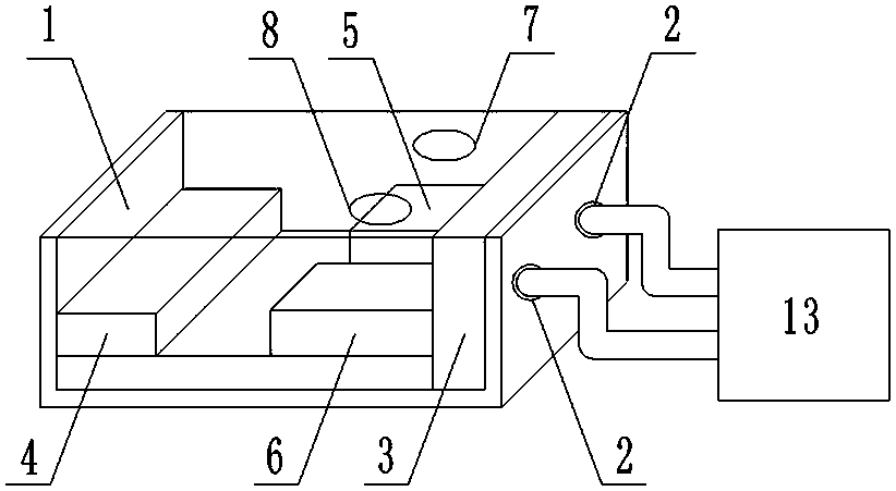
[0072] Such as Figure 1 to Figure 5 As shown, the magnetic vibration effect imprint sensor of the present invention includes a housing 1, and one end of the housing 1 is provided with a data output port 2, and the field communication bus is connected to the central controller 3 through the data output port 2;

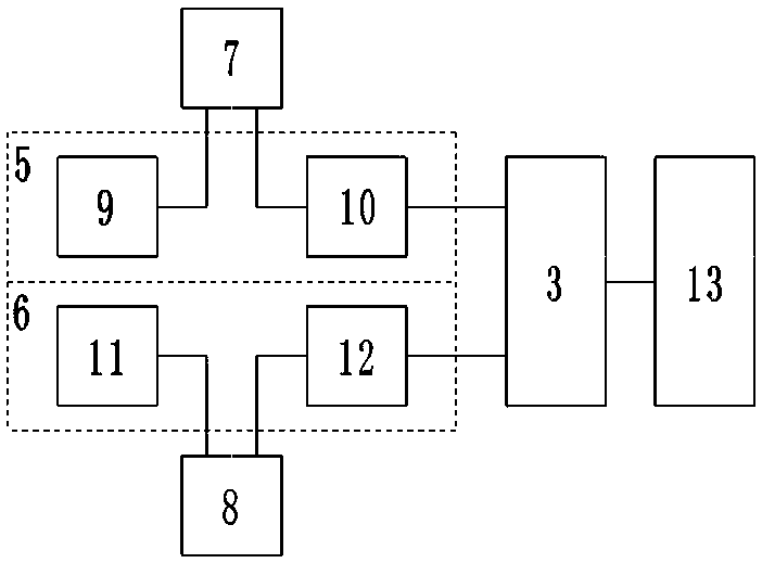
[0073] The central controller 3 is arranged on one side of the housing 1, and the other side of the housing 1 is provided with a magnet bar 4, and a pair of sensing modules are arranged in parallel between the central controller 3 and the magnet bar 4, Including a first magnetoelastic ion imprint sensing module 5 and a second magnetoelastic ion imprint sensing module 6;

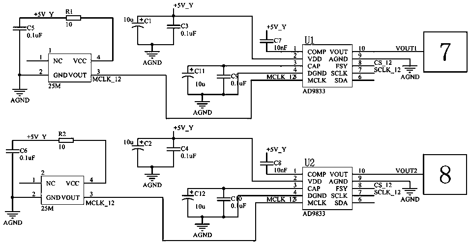
[0074] A first coil 7 is also arranged above the first magnetoelastic ion imprint sensing module 5, and a second coil 8 is also arranged above the second magnetoelastic ion imprint sensing module 6;

[0075] The first magnetoelastic ion imprint sensing module 5 includes a first waveform generation mo...


PUM


Abstract

The invention provides a magnetic resonance effect based imprinting sensor and belongs to the technical field of the magnetic resonance effect based imprinting sensor in order to provide the magneticresonance effect based imprinting sensor which is high in detection speed, high in precision and high in detection flexibility. According to the technical scheme for realizing the technical effects, the magnetic resonance effect based imprinting sensor comprises a casing, wherein data output ports are formed in one end of the casing, and a field communication bus is connected with a central control unit through the data output ports; the central control unit is arranged on one side of the casing, a magnet strip is arranged on the other side of the casing, and a pair of sensing modules are arranged between the central control unit and the magnet strip in parallel and comprises a first magneto-elastic ionic imprinting sensing module and a second magneto-elastic ionic imprinting sensing module; a first coil is arranged above the first magneto-elastic ionic imprinting sensing module, and a second coil is arranged above the second magneto-elastic ionic imprinting sensing module. The magnetic resonance effect based imprinting sensor is applied to ion solution concentration detection.

Description

technical field [0001] The magnetic vibration effect imprint sensor of the invention belongs to the technical field of magnetic vibration effect imprint sensor. Background technique [0002] Molecular imprinting technology is a process of preparing and synthesizing a polymer that has a selective recognition effect on a specific imprinted molecule. The prepared polymer is a molecularly imprinted polymer. Advantages such as chemical stability are playing an increasingly important role in biosensors. Molecular imprinting technology, as a new type of detection and analysis technology, has an important application prospect in the identification and analysis of substances; [0003] Biosensors use organisms or immobilized biological components as sensitive elements, but in practical applications, due to the instability of biological components, biosensors have the disadvantages of poor compatibility, low sensitivity and high production costs; in recent years, molecular imprinting ...

Claims


Application Information

Patent Timeline
Patent Type & Authority Applications(China)
IPC IPC(8): G01N24/00
CPCG01N24/00
Inventor 袁仲云李宇超桑胜波禚凯张虎林张强
Owner TAIYUAN UNIV OF TECH
Why Eureka
Try Eureka