Online monitoring method for partial discharge of high-voltage feeder cables of electrified railway

A technology of electrified railway and partial discharge, applied in the direction of test circuit, measuring electricity, measuring device, etc., can solve the problems of large noise, few related documents, large error of discharge signal, etc., and achieve the effect of preventing breakdown accidents

Inactive Publication Date: 2018-11-13
西安开天电气可靠性实验室有限公司
View PDF7 Cites 1 Cited by
  • Summary
  • Abstract
  • Description
  • Claims
  • Application Information

AI Technical Summary

Problems solved by technology

[0004] The search found that there are many patents and documents in the prior art for researching on-line partial discharge monitoring devices and methods for power cables, but there are few on-line partial discharge monitoring devices and methods for high-voltage feeder cables in electrified railway traction systems, and there are not many related documents. In the title "A Traction Substation Feeder Cable Partial Discharge Monitoring Device and Its Monitoring Method" (application date is November 20, 2013, application number is 201310591045.6, application publication date is March 5, 2014, publication number In the patent of CN103616620A), all described feeder cable partial discharge monitoring methods use sound sensors and temperature sensors to extract signals. Only when the internal insulation defects of the cable develop to a relatively serious level, or even close to the edge of breakdown, can there be Visible sound and vibration signals
Moreover, since the cables are mostly laid outdoors, the noise is relatively high, and the partial discharge signal tested by the sound and vibration sensors has a large error

Method used


Image

  • Online monitoring method for partial discharge of high-voltage feeder cables of electrified railway
  • Online monitoring method for partial discharge of high-voltage feeder cables of electrified railway
  • Online monitoring method for partial discharge of high-voltage feeder cables of electrified railway

Examples


Embodiment Construction

[0020] The present invention will be described in detail below in conjunction with the accompanying drawings and specific embodiments.

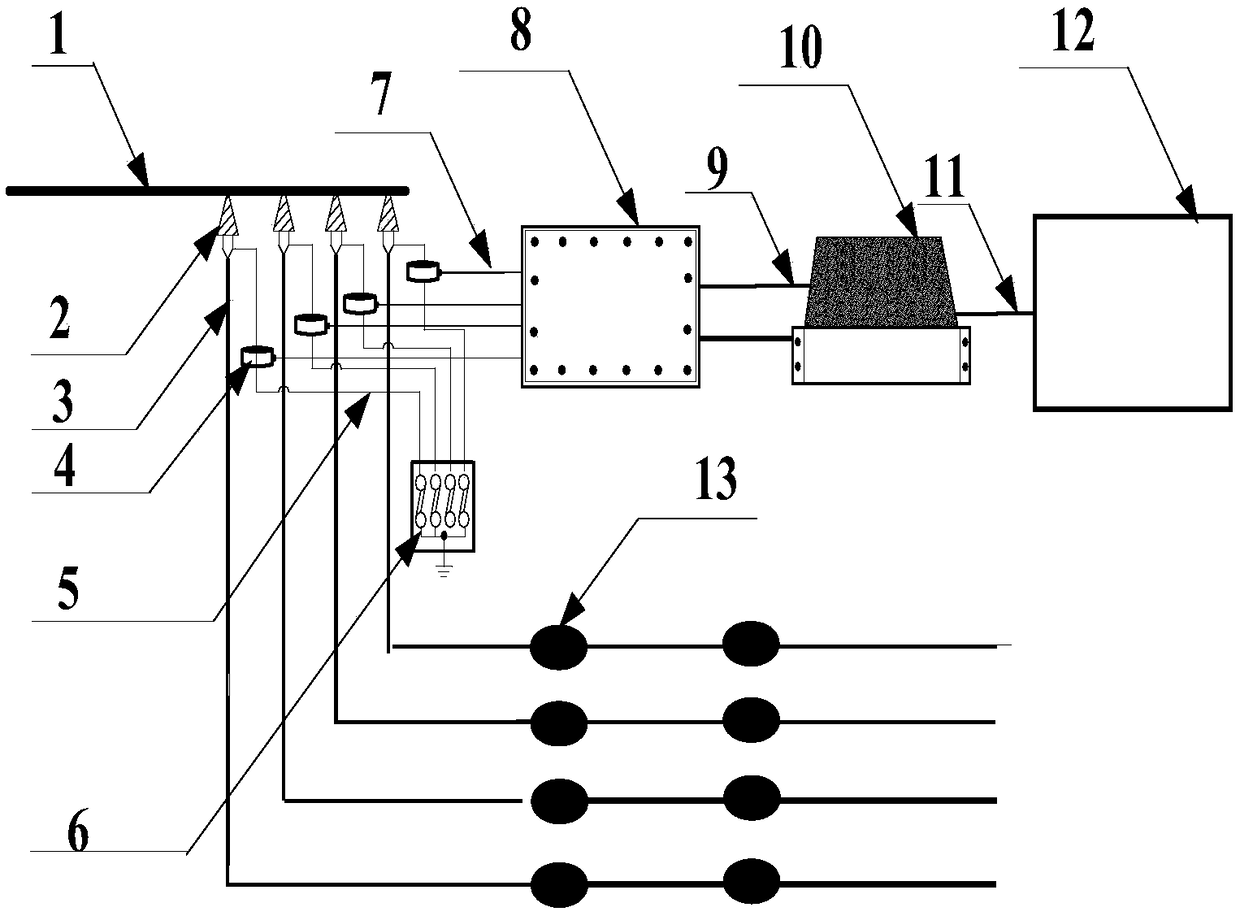
[0021] The invention provides an on-line monitoring method for partial discharge of high-voltage feeder cables of electrified railways. figure 1 As shown, the bare conductor 1 of the railway locomotive power supply feeder in the figure is connected to the railway catenary at one end, and connected to the feeder cable connector 2 at the other end, and the feeder cable connector 2 is connected to the feeder cable 3, and is connected to the traction transformer , each cable joint 2 has a cable grounding wire 5 grounded through the grounding box 6, forming a connection mode from the traction transformer to the primary equipment of the feeder section.

[0022] This embodiment takes four high-voltage feeder cables 3 as an example for illustration. This embodiment uses four high-frequency current transformers 4 (HFCT) clamped on each cable grounding...


PUM


Abstract

The invention discloses an online monitoring method for partial discharge of high-voltage feeder cables of an electrified railway. The method comprises the following steps: high-frequency current transformers are arranged on cable grounding wires of multiple high-voltage feeder cables; the high-frequency current transformers acquire partial discharge signals of the cables synchronously and send the signals to an acquisition unit for processing through coaxial lines with equal length; the acquisition unit sends multiple processed partial discharge signals of the cables to a monitoring main unit, and the monitoring main unit judges the high-voltage feeder cables which have partial discharge through analysis. The problem of inaccurate partial discharge testing of the cables due to same-phaseside-by-side laying of the multiple feeder cables and the problem of response lag in conventional fiber temperature detection are solved, complicated field manual operation is not needed, all that isneeded is to synchronously acquire the partial discharge signals at a high speed through high-speed multiple channels and analyze signal amplitude and delay conditions so as to test partial dischargeof each cable of the same phase rapidly, insulation status of the cables is evaluated, and breakdown accidents are prevented.

Description

technical field [0001] The invention belongs to the technical field of insulation testing of electrified railway high-voltage lines, and in particular relates to an on-line monitoring method for partial discharge of electrified railway high-voltage feeder cables. Background technique [0002] With the rapid development of high-speed rail, high-voltage feeder cables have been widely used in electrified railway traction power supply systems. The catenary is to supply power to the locomotive in the form of bare wires. The electric energy output from the transformer end of the substation often needs to be transmitted underground in the form of cables because of bridging some buildings or obstacles, so feeder cables came into being. In the early stage of high-speed rail development There is no 27.5kV power cable specially designed for railway applications, and it is often replaced by ordinary 35kV XLPE cables and used in large quantities. The load current of the traction power s...

Claims


Application Information

Patent Timeline
Patent Type & Authority Applications(China)
IPC IPC(8): G01R31/12G01R31/14
CPCG01R31/1272G01R31/14
Inventor 王天凤樊会娟李甲张佩
Owner 西安开天电气可靠性实验室有限公司
Why Eureka
Try Eureka