Eureka AIR delivers breakthrough ideas for toughest innovation challenges, trusted by R&D personnel around the world.

Exposure machine for effectively preventing photoresist from polluting mask plate

A mask and photoresist technology, applied in the field of exposure machines, can solve the problems of reducing exposure effect, mask contamination, increasing photoresist uniformity, etc., achieving good exposure effect, improving clarity, and preventing pollution. Effect

Inactive Publication Date: 2018-11-13
何琪
View PDF0 Cites 0 Cited by
  • Summary
  • Abstract
  • Description
  • Claims
  • Application Information

AI Technical Summary

Problems solved by technology

[0005] Aiming at the deficiencies of the prior art, the present invention provides an exposure machine that can effectively prevent photoresist from polluting the mask, which can effectively prevent photoresist from polluting the mask, improve the definition of exposure patterns, and have better exposure effects. , reduce ultraviolet energy, absorb ultraviolet rays, increase the uniformity of photoresist distribution on the substrate surface, reduce the fluidity of photoresist distribution on the substrate surface, absorb xylene volatilized from photoresist, etc., which solves the problem of easy masking Contaminated by photoresist, which reduces its service life and exposure clarity, thereby reducing the exposure effect

Method used


Image

  • Exposure machine for effectively preventing photoresist from polluting mask plate
  • Exposure machine for effectively preventing photoresist from polluting mask plate
  • Exposure machine for effectively preventing photoresist from polluting mask plate

Examples


Embodiment Construction

[0038] The following will clearly and completely describe the technical solutions in the embodiments of the present invention with reference to the accompanying drawings in the embodiments of the present invention. Obviously, the described embodiments are only some, not all, embodiments of the present invention. Based on the embodiments of the present invention, all other embodiments obtained by persons of ordinary skill in the art without making creative efforts belong to the protection scope of the present invention.

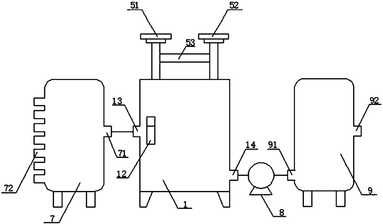
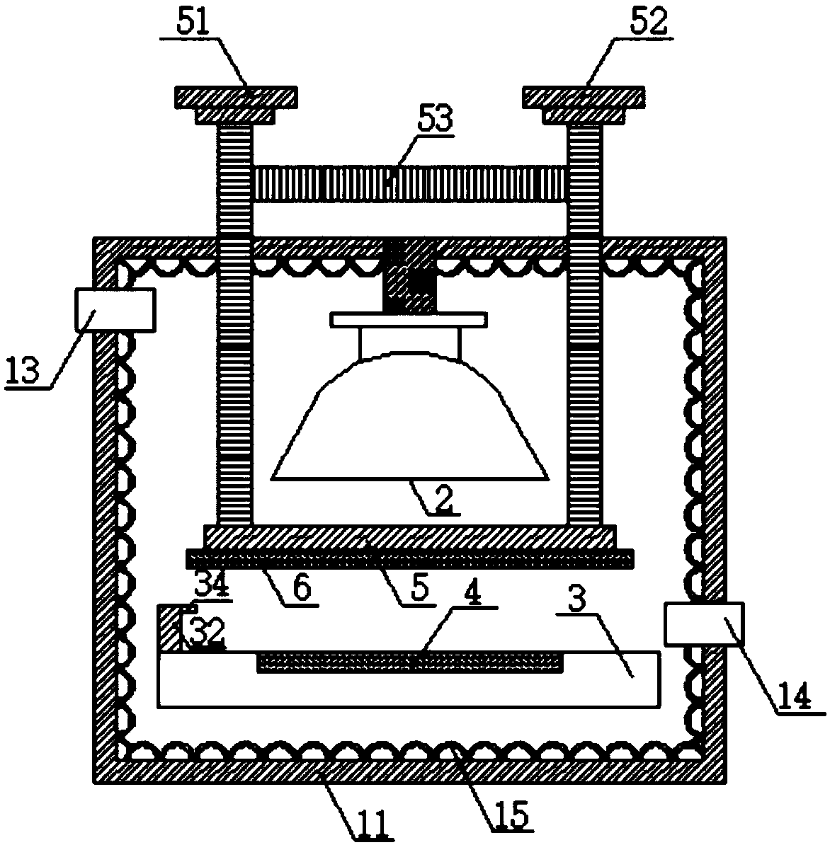
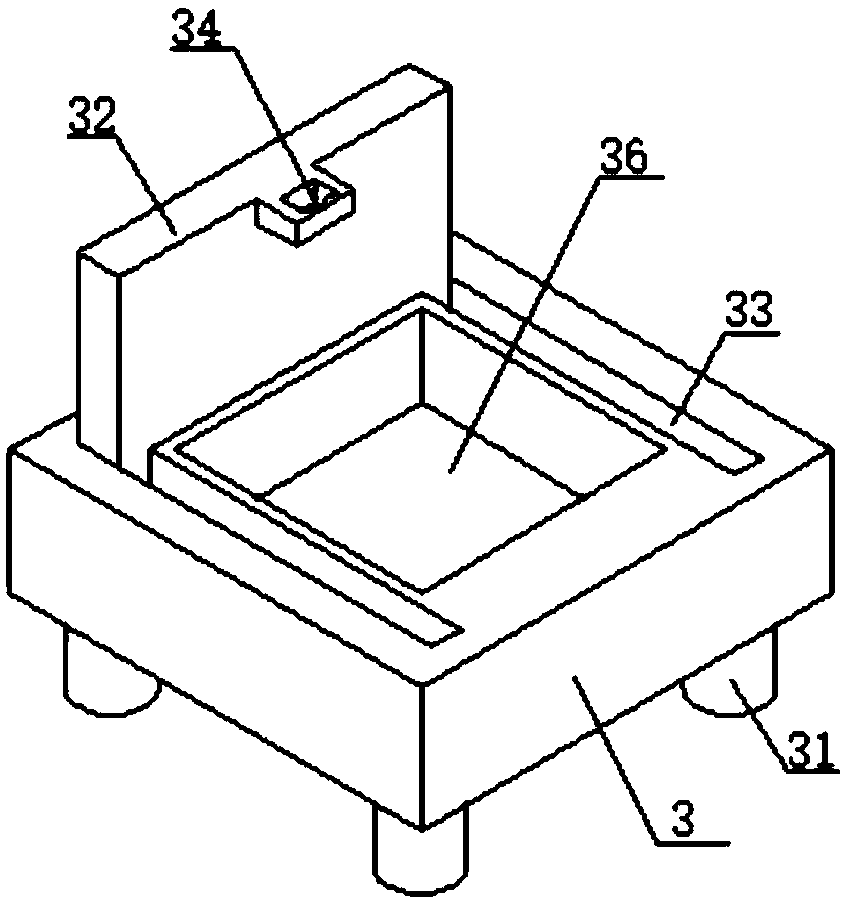
[0039] A kind of exposure machine that effectively prevents photoresist from contaminating the mask plate, see figure 1, including an exposure device 1, the exposure device 1 includes a box body 11, a box door is opened on the front side wall of the box body 11, one side of the box door is hinged with the box body 11 through a hinge, and the other side is connected with the box body by a pressing spring. The body 11 is not fixedly connected, and a box door han...


PUM


Abstract

The invention relates to the technical field of explosion equipment and discloses an exposure machine for effectively preventing a photoresist from polluting a mask plate. The exposure machine comprises an exposure device; the exposure device comprises a box body; an ultra-pressure mercury lamp is fixedly mounted at the top in the box body; the mask plate is arranged under the ultra-high pressuremercury lamp; a first pressing rod and a second pressing rod are symmetrically arranged in the middle of both sides of the mask plate respectively; an explosion platform is arranged under the mask plate; a groove is formed in the upper surface of the explosion platform; a substrate is arranged inside the groove; symmetric guide track grooves are respectively formed in both sides of the groove; sliding blocks which are symmetrically arranged on both sides of the bottom end of a scraper plate are connected inside the guide track grooves in a sliding manner respectively; a light permeable plate is arranged between the substrate and t he mask plate; a first vent hole in the left side wall of the tank body is connected with a cold air hole of a refrigeration device; and a second vent hole in the right side wall of the tank body is connected with an air inlet of a gas purification device through an air guide tube with an exhaust pump. By adopting the exposure machine, the problem that the mask plate can be easily polluted by a photoresist is solved.

Description

technical field [0001] The invention relates to the technical field of exposure equipment, in particular to an exposure machine for effectively preventing photoresist from polluting a mask plate. Background technique [0002] Exposure machine refers to the machine equipment that transfers the image information on the film or other transparent body to the surface coated with photosensitive material by turning on the light and emitting ultraviolet rays of UVA wavelength. [0003] During the working process of the exposure machine, when the mask plate is in direct contact with the photoresist layer, the exposed pattern is equivalent to the pattern resolution on the mask plate, but the mask plate is directly in contact with the photoresist layer, and the mask plate It is easy to be polluted by photoresist, and then accelerates the wear of the mask plate, making the mask plate easily damaged, thereby reducing the clear image of the exposed pattern, resulting in the technical prob...

Claims


Application Information

Patent Timeline
IPC IPC(8): G03F7/20
CPCG03F7/70916G03F7/70808G03F7/70858G03F7/70933
Inventor 何琪
Owner 何琪
Why Eureka
Eureka Blog
Learn More