Lithium core battery pack convenient to replace

A technology that facilitates the replacement of lithium batteries. It is applied in the direction of battery pack components, secondary batteries, and secondary battery repair/maintenance. It can solve problems such as battery performance degradation, impact on battery pack performance, and inconvenient replacement and maintenance of lithium batteries. To achieve the effect of convenient operation

Active Publication Date: 2018-11-13
安徽相源新能源有限公司
4 Cites 8 Cited by

AI-Extracted Technical Summary

Problems solved by technology

[0004] However, the above solution has the following defects in use: during long-term use of the lithium battery pack, due to the difference in the quality of the lithium battery cells, the performance of the battery will decline to var...

Method used

Both sides surfaces of described inner housing 12 are all integrally provided with slide rail 13, and the inner cavity side wall of described outer shell 1 is provided with the chute 15 that matches with slide rail 13, utilizes slide rail 13 , the inner casing 12 can be easily pushed into the outer casing 1, and at the same time, the sliding rail 13 and the chute 15 can cooperate to prevent the inner casing 12 from shaking and improve the stability.
Concretely, during use, the lithium battery core body 14 is respectively installed in the lithium battery core installation groove 8, after the installation is completed, the inner housing 12 is pushed into the outer housing 1 inside along the slide rail 13, when the inner housing 12 When the outer casing 1 is pushed into contact with the block 16, the block 2 will be pushed up along the bevel on the block 16 until the block 16 enters the slot 5, under the action of the second spring 17, The clamping block 16 at the end of the clamping plate 2 can be automatically pushed into the clamping groove 5 on the inner housing 12, the inner housing 12 is automatically clamped, the clamping plate 2 is pressed, and the clamping block 16 comes out of the clamping groove 5, At the same time, push the push plate 4 under the action of the first spring 3 to automatically push the inner casing 12 out, and the inner casing 12 is conveniently taken out through the handle 10 to replace the lithium battery cell body 1...

Abstract

The invention discloses a lithium core battery pack convenient to replace. The lithium core battery pack includes an outer casing and an inner casing. The inner casing is movably disposed in the outercasing, the surfaces of the two sides of the inner casing are provided with lithium core mounting grooves for placing lithium core bodies, an upper electrical contact and a lower electrical contact are fixed at the upper end and the lower end of each lithium core mounting groove respectively, the end of the outer casing is rotatably connected with a clamping plate, one end of the clamping plate is movably clamped with the inner casing, and the bottom of an inner chamber of the outer casing is fixedly connected with a push plate through a first spring. According to the lithium core battery pack, through mutual matching of a sliding rail and a sliding groove, the inner casing is conveniently pushed into the outer casing, a clamping block at the end of the clamping plate can be pushed automatically into the clamping groove of the inner casing under the action of a second spring, to clamp the inner casing; by pressing of the clamping plate, the clamping block is separated from the clamping groove; at the same time, under the action of the first spring, the push plate is driven to automatically push the inner casing out, and the inner casing is taken out conveniently through a handle to replace the lithium core bodies.

Application Domain

Cell component detailsSecondary cells servicing/maintenance

Technology Topic

LithiumSoftware engineering +2

Image

  • Lithium core battery pack convenient to replace
  • Lithium core battery pack convenient to replace
  • Lithium core battery pack convenient to replace

Examples

  • Experimental program(1)

Example Embodiment

[0021] The technical solutions in the embodiments of the present invention will be clearly and completely described below in conjunction with the embodiments of the present invention. Apparently, the described embodiments are only some of the embodiments of the present invention, not all of them. Based on the embodiments of the present invention, all other embodiments obtained by persons of ordinary skill in the art without making creative efforts belong to the protection scope of the present invention.
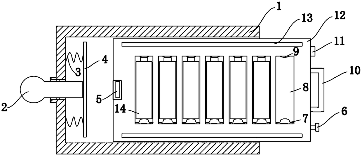
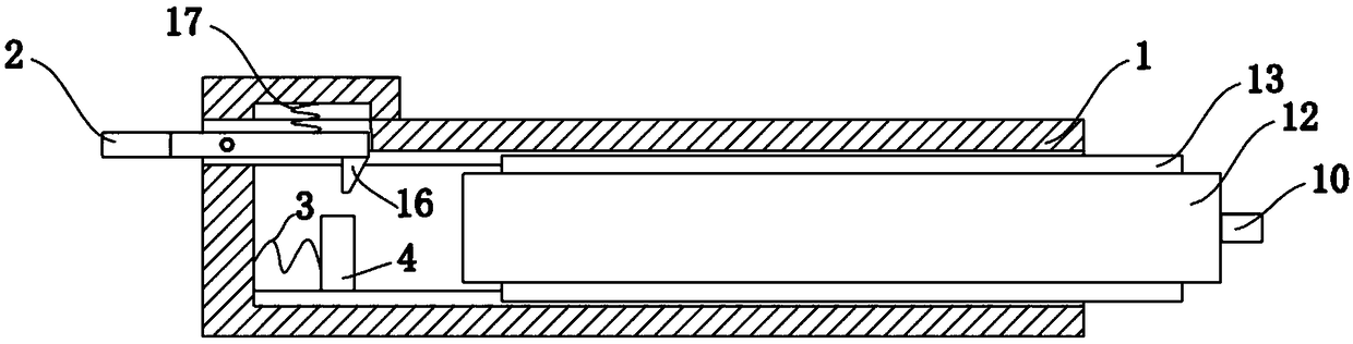
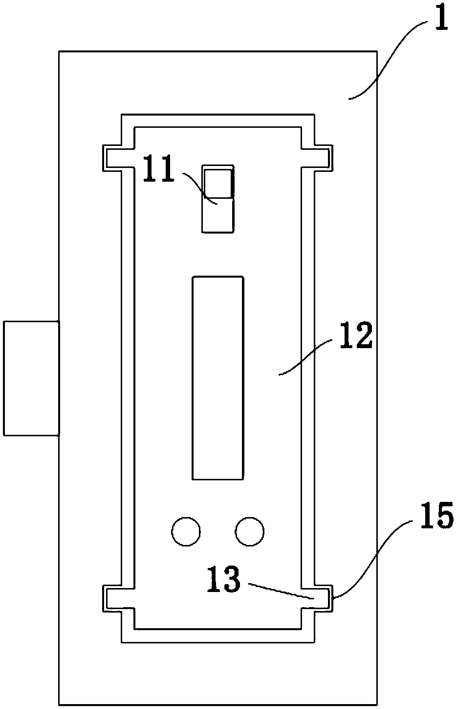
[0022] like Figure 1-5 As shown, a convenient replacement lithium cell battery pack includes an outer casing 1 and an inner casing 12, the inner casing 12 is movably arranged inside the outer casing 1, and both sides of the inner casing 12 are provided with There is a lithium battery cell installation groove 8 for placing the lithium battery cell body 14. The upper and lower ends of the lithium battery cell installation groove 8 are respectively fixed with an upper electrical contact piece 9 and a lower electrical contact piece 7, and the outer end of the inner casing 12 is in turn A terminal bolt 6, a handle 10 and a control switch 11 are installed, and the end of the outer shell 1 is rotatably connected with a clamping plate 2, and one end of the clamping plate 2 is movably engaged with the inner shell 12, and the outer shell 1 The bottom of the inner cavity is fixedly connected with a push plate 4 through a first spring 3 .
[0023] Both sides of the inner casing 12 are integrally provided with slide rails 13, and the inner cavity side wall of the outer casing 1 is provided with a slide groove 15 matched with the slide rails 13, and the slide rails 13 can be used to facilitate The inner housing 12 is pushed into the outer housing 1, and at the same time, the slide rail 13 cooperates with the chute 15 to prevent the inner housing 12 from shaking and improve the stability.
[0024] The upper electrical contact piece 9 and the lower electrical contact piece 7 are closely attached to the positive and negative poles of the lithium cell body 14 respectively, and the upper electrical contact piece 9 and the lower electrical contact piece 7 are connected with a terminal bolt 6 and a control switch 11 through a wire. , the upper electrical contact piece 9 and the lower electrical contact piece 7 are both pressed and formed by copper sheets, and have good electrical conductivity. The lithium battery body 14 is clamped in the lithium battery installation groove 8 through the upper electrical contact piece 9 and the lower electrical contact piece 7, Easy to assemble and disassemble.
[0025] One side of the inner housing 12 is provided with a card slot 5, and one end of the inner side of the card plate 2 is integrally provided with a card block 16, and the card block 16 is engaged with the card slot 5, and the card block 16 is Wedge shape, when the inner housing 12 is pushed into the outer housing 1, the inner housing 12 pushes up the clamping plate 2 along the hypotenuse on the clamping block 16 until the clamping block 16 enters the slot 5, the second spring 17 Under the push of the inner casing 12, the inner housing 12 can be fixed.
[0026] The end of the clamp 2 protruding from the outer shell 1 is provided with an anti-slip pattern, which is convenient for pressing the clamp 2 and avoiding slipping. The second spring 17, through the second spring 17, the block 16 at the end of the clamping plate 2 can be automatically pushed into the slot 5 on the inner housing 12, and the inner housing 12 is automatically clamped.
[0027] The length of the push plate 4 is the same as that of the inner housing 1 , and two first springs 3 are provided and located at both ends of the push plate 4 .
[0028] The depth of the lithium battery cell installation groove 8 is the same as the diameter of the lithium battery cell body 14. When the inner casing 12 is pushed into the outer casing 1, the lithium battery cell body 14 can be stably kept in the lithium battery cell installation groove 8 by using the outer casing 1 , to prevent the lithium battery core body 14 from coming out.
[0029] Specifically, when in use, the lithium battery core bodies 14 are respectively installed in the lithium battery cell installation slots 8. After the installation is completed, the inner housing 12 is pushed into the outer housing 1 along the slide rail 13. When the inner housing 12 is pushed into the outer housing When the body 1 is in contact with the clamping block 16, the clamping plate 2 will be pushed up along the hypotenuse on the clamping block 16 until the clamping block 16 enters the clamping groove 5, under the action of the second spring 17, the clamping plate 2 can be pushed up. The block 16 at the end of the plate 2 is automatically pushed into the slot 5 on the inner casing 12, automatically clamps the inner casing 12, presses the clip 2, and the block 16 comes out of the slot 5, and at the same time, Under the action of the first spring 3, the push plate 4 is pushed to automatically push out the inner casing 12, and the inner casing 12 is conveniently taken out through the handle 10 to replace the lithium battery cell body 14. Lithium cell bodies 14 are used in series or in parallel through wires, which can be connected according to the conditions of use. Connect the electrical equipment to the terminal bolt 6 to complete the connection, and use the control switch 11 to realize the opening and closing of the circuit, which is easy to operate.
[0030] Finally, it should be noted that: the above is only a preferred embodiment of the present invention, and is not intended to limit the present invention. Although the present invention has been described in detail with reference to the foregoing embodiments, for those skilled in the art, it still The technical solutions recorded in the foregoing embodiments may be modified, or some of the technical features may be replaced by equivalents. Any modifications, equivalent replacements, improvements, etc. made within the spirit and principles of the present invention shall be included in the within the protection scope of the present invention.

PUM

no PUM

Description & Claims & Application Information

We can also present the details of the Description, Claims and Application information to help users get a comprehensive understanding of the technical details of the patent, such as background art, summary of invention, brief description of drawings, description of embodiments, and other original content. On the other hand, users can also determine the specific scope of protection of the technology through the list of claims; as well as understand the changes in the life cycle of the technology with the presentation of the patent timeline. Login to view more.

Similar technology patents

Laser radar optical system with optical axis calibrating function and optical axis calibrating method

InactiveCN102353950AOptical axis alignment with high precisioneasy to operate
Owner:INST OF APPLIED ELECTRONICS CHINA ACAD OF ENG PHYSICS +1

Defrosting control method and device

ActiveCN104807132Aeasy to operateDefrost is reasonable
Owner:GREE ELECTRIC APPLIANCES INC OF ZHUHAI

Classification and recommendation of technical efficacy words

  • easy to operate

Lancet device

InactiveUS7303573B2inexpensively mass-producedeasy to operate
Owner:ABBOTT DIABETES CARE INC

Rapid and non-invasive optical detection of internal bleeding

InactiveUS20050065436A1easy to operaterapid and accurate result
Owner:HO WINSTON ZONH +2
Why Eureka
Try Eureka