Material conveying method of removal tower

A removal tower and removal technology, applied in separation methods, chemical instruments and methods, dispersed particle separation, etc., can solve the problem of secondary recycling and environmental protection of unfavorable removers, large powder removal of removers, and removal of It can improve the secondary utilization rate, reduce environmental pollution and reduce the wear rate.

Active Publication Date: 2018-11-16
钢研晟华科技股份有限公司
View PDF10 Cites 2 Cited by
  • Summary
  • Abstract
  • Description
  • Claims
  • Application Information

AI Technical Summary

Problems solved by technology

[0003] In view of the above analysis, the present invention aims to provide a method for removing materials from the removal tower, which is used to solve the serious wear and tear of the existing removal agent during the removal of materials in the removal tower, resulting in large powdering of the removal agent, which is not conducive to removal. Secondary Recycling of Removing Agents and Technical Problems of Environmental Protection

Method used


Image

  • Material conveying method of removal tower
  • Material conveying method of removal tower

Examples


Embodiment 1

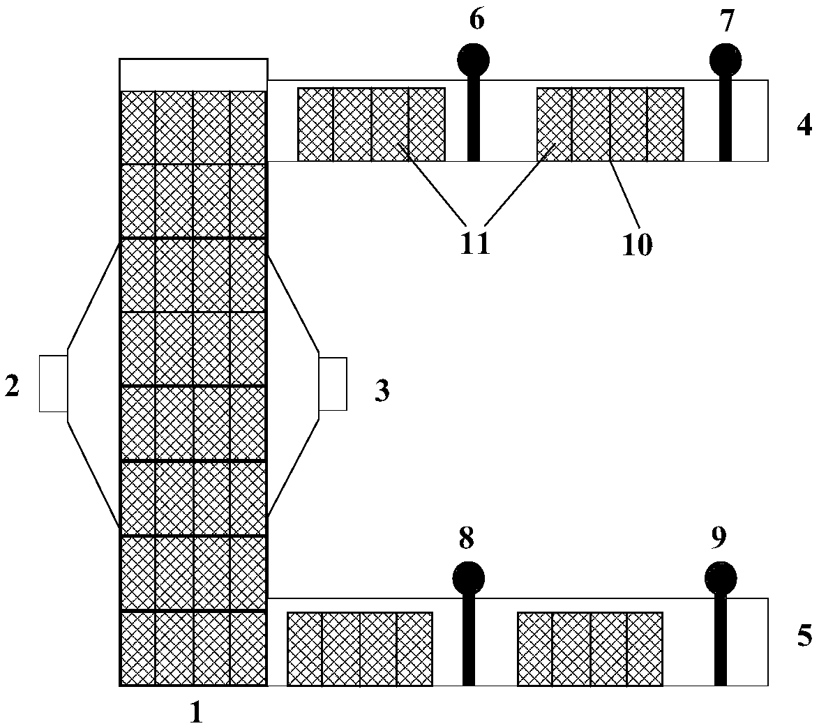
[0045] combine figure 1 , the present embodiment adopts the first type of removal unit cell 10 to carry out the removal treatment, the surface connecting the gas inlet 2 and the gas outlet 3 with the tower body is a steel plate, and the mesh diameter of the steel plate is 5mm; the gas inlet 2 and the gas outlet 3 are respectively arranged on both sides of the removal tower 1, and the gas flows in the horizontal direction in the removal tower 1. In this embodiment, the first type of removal unit cell 10 is provided with 3 vertical and 3 horizontal unit middle plates, the unit middle plate is a steel plate with mesh, and the mesh diameter is 8mm; a pair of side faces in the unit cell 10 are removed It is a steel plate with a mesh, the mesh diameter is 8mm, and the rest of the surface is an airtight sealing steel plate. The gas removal agent is active coke, which is cylindrical, with a diameter of 10mm and a height of 12mm. Gas inlet 2 SO 2 The content is 600mg / m 3 .

[0046...

Embodiment 2

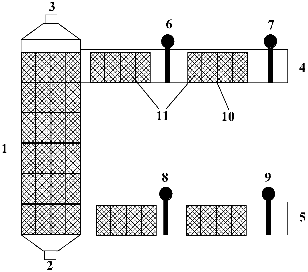
[0056] combine figure 2 , the present embodiment adopts the second type of removal unit cell 10 to carry out the removal treatment, the surface connected to the tower body by the gas inlet 2 and the gas outlet 3 is a steel plate, and the mesh diameter of the steel plate is 5mm; the gas inlet 2 and the gas outlet 3 are respectively arranged at the bottom and top of the removal tower 1, and the gas flows in the vertical direction in the removal tower 1. The second type of removal unit cell 10 adopted in this embodiment is provided with 3 vertical and 3 horizontal unit middle plates, the unit middle plate is a steel plate with mesh, and the mesh diameter is 8mm; remove the top surface and The side in the direction of the bottom is a steel plate with mesh, the mesh diameter is 8mm, and the side in the other direction is an airtight sealing steel plate. The gas removal agent is active coke, which is cylindrical, with a diameter of 10mm and a height of 14mm. Gas inlet 2 SO 2 The...


PUM


Abstract

The invention relates to a material conveying method of a removal tower, and belongs to the technical field of removal of air pollutants. The material conveying method solves the problems of serious abrasion of a removal agent in the removal tower, serious chalking of the removal agent, and failure to reach secondary recycling of removal agent and environment protection in the prior art. The material conveying method of the removal tower comprises the following steps of S1, charging of material: enabling a removal unit grid to enter the removal tower via a material charge channel; S2, fallingof material: enabling the removal unit grid to fall onto the bottom part of the removal tower via the top part of the removal tower along a material falling channel; S3, discharging of material: discharging the removal unit grid out of the removal tower via a material discharge channel. The material conveying method has the advantages that the removal agent is loaded into the fixed type removal unit grid, and the movement type of the removal unit grid is controlled to replace the removal agent; the abrasion of the removal agent in the use process is reduced, the secondary recycling rate of theremoval agent is improved, and the use cost of the removal agent is reduced.

Description

technical field [0001] The invention relates to the technical field of gas pollutant removal and treatment, in particular to a material delivery method for a removal tower. Background technique [0002] At present, the feeding method of the existing continuous feeding removal tower is as follows: the removal agent is directly added into the removal tower from the top, and the granular removal agent slowly flows from the top of the removal tower to the bottom, and the particles are continuously fed. , continuous flow, and continuous discharge will cause the wear of the remover, and the general wear rate is higher than 3%, which will cause large powdering of the remover, which is not conducive to the secondary recovery of the remover, and is also not conducive to the surrounding environment Protect. Contents of the invention [0003] In view of the above analysis, the present invention aims to provide a method for removing materials from the removal tower, which is used to ...

Claims


Application Information

Patent Timeline
Patent Type & Authority Applications(China)
IPC IPC(8): B01D53/00
CPCB01D53/00
Inventor 王锋高建军张俊严定鎏齐渊洪林万舟
Owner 钢研晟华科技股份有限公司
Why Eureka
Try Eureka