Control system of 3D laser carving machine

A control system, three-dimensional laser technology, applied in the direction of laser welding equipment, manufacturing tools, connecting device components, etc., can solve problems such as unstable plugging force, user electric shock, user safety accidents, etc., to achieve the level of automation High, increase the service life, the effect of preventing electric shock accidents

Inactive Publication Date: 2018-11-16
广州广林科技有限公司
View PDF0 Cites 1 Cited by
  • Summary
  • Abstract
  • Description
  • Claims
  • Application Information

AI Technical Summary

Problems solved by technology

[0002] At present, the use of three-dimensional laser engraving machines is gradually replacing traditional engraving machines. The existing three-dimensional laser engraving machines are manually plugged and unplugged by personnel when they are powered on. The generation of electric arc is easy to cause electric shock to the user, which has a certain potential danger to the user, which will cause safety accidents and cause casualties, and the force of the personnel is unstable when plugging in, which is easy to cause damage to the equipment. Moreover, the traditional power connection port is usually not closed Protection measures, the exposure of the power connection port is easy to enter dust, etc., which will affect the service life

Method used


Image

  • Control system of 3D laser carving machine
  • Control system of 3D laser carving machine
  • Control system of 3D laser carving machine

Examples


Embodiment Construction

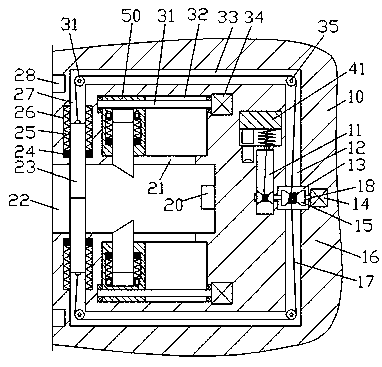
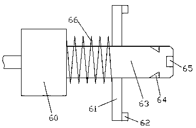
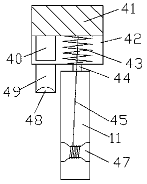
[0017] Combine below Figure 1-4 The present invention will be described in detail.

[0018] refer to Figure 1-4 , according to an embodiment of the present invention, a control system for a three-dimensional laser engraving machine includes a base 10 and a connecting portion 60 connected to the base 10 by plugging and fitting, and the left end surface of the base 10 is provided with a Insertion cavity 22, the inner wall of the right side of the insertion cavity 22 is fixed with a power connection block 20, the upper and lower inner walls of the insertion cavity 22 are symmetrically provided with first sliding grooves 27, and the first sliding groove 27 is slidably fitted with The cover plate 23, the inner walls of the left and right sides of the first sliding joint groove 27 are symmetrically provided with first guide grooves 26, and the first guide groove 27 is slidably fitted with a first A guide block 24, the side of the first guide block 24 far away from the insertion ...


PUM


Abstract

The invention discloses a control system of a 3D laser carving machine. The control system comprises a base and a connecting part connected to the base in an inserted and matched mode. The end face ofthe left side of the base is provided with an insertion cavity. An electric connecting block is fixedly arranged on the inner wall of the right side of the insertion cavity. The upper and lower innerwalls of the insertion cavity are internally and symmetrically provided with first sliding grooves. Cover plates are mounted in the first sliding grooves in a sliding fit mode. The inner walls of theleft and right sides of each first sliding groove are internally and symmetrically provided with first guide grooves. First guide blocks fixedly connected with the cover plates are mounted in the first guide grooves in a sliding fit mode. The sides, far away from the insertion cavity, of the first guide blocks abut against and are connected with first compression springs in a matched mode. The tail end of the side, far away from the insertion groove, of each first sliding groove extends rightwards to be provided with a second sliding groove.

Description

technical field [0001] The invention relates to the technical field of laser engraving, in particular to a control system for a three-dimensional laser engraving machine. Background technique [0002] At present, the use of three-dimensional laser engraving machines is gradually replacing traditional engraving machines. The existing three-dimensional laser engraving machines are manually plugged and unplugged by personnel when they are powered on. The generation of electric arc is easy to cause electric shock to the user, which has a certain potential danger to the user, which will cause safety accidents and cause casualties, and the force of the personnel is unstable when plugging in, which is easy to cause damage to the equipment. Moreover, the traditional power connection port is usually not closed Protective measures, the exposed UPC port is easy to enter dust, etc., which will affect the service life. Contents of the invention [0003] The object of the present inven...

Claims


Application Information

Patent Timeline
Patent Type & Authority Applications(China)
IPC IPC(8): B23K26/70B23K26/362H01R13/52H01R13/627H01R13/629H01R13/66H01R13/70
CPCB23K26/702B23K26/361H01R13/5213H01R13/6278H01R13/629H01R13/6633H01R13/701
Inventor 黎莲珍
Owner 广州广林科技有限公司
Why Eureka
Try Eureka