
A circular stainless steel common plate flange air duct welding connection mechanism

A common plate flange and welding connection technology, applied in welding equipment, auxiliary welding equipment, welding/cutting auxiliary equipment, etc., can solve the problems of inconvenient air duct flip welding, etc., achieve convenient rotation welding, reduce labor intensity, improve The effect of welding quality

Active Publication Date: 2021-01-22
中创博瑞建设工程有限公司
View PDF6 Cites 0 Cited by
  • Summary
  • Abstract
  • Description
  • Claims
  • Application Information

AI Technical Summary

Problems solved by technology

[0004] The purpose of the present invention is to solve the problem in the prior art that it is inconvenient to turn over and weld the air pipe when clamping, and propose a circular stainless steel common plate flange air pipe welding connection mechanism

Method used


Image

  • A circular stainless steel common plate flange air duct welding connection mechanism
  • A circular stainless steel common plate flange air duct welding connection mechanism

Examples


Embodiment Construction

[0018] The following will clearly and completely describe the technical solutions in the embodiments of the present invention with reference to the accompanying drawings in the embodiments of the present invention. Obviously, the described embodiments are only some, not all, embodiments of the present invention.

[0019] In describing the present invention, it should be understood that the terms "upper", "lower", "front", "rear", "left", "right", "top", "bottom", "inner", " The orientation or positional relationship indicated by "outside", etc. is based on the orientation or positional relationship shown in the drawings, and is only for the convenience of describing the present invention and simplifying the description, rather than indicating or implying that the referred device or element must have a specific orientation, so as to Specific orientation configurations and operations, therefore, are not to be construed as limitations on the invention.

[0020] refer to Figure ...


PUM


Abstract

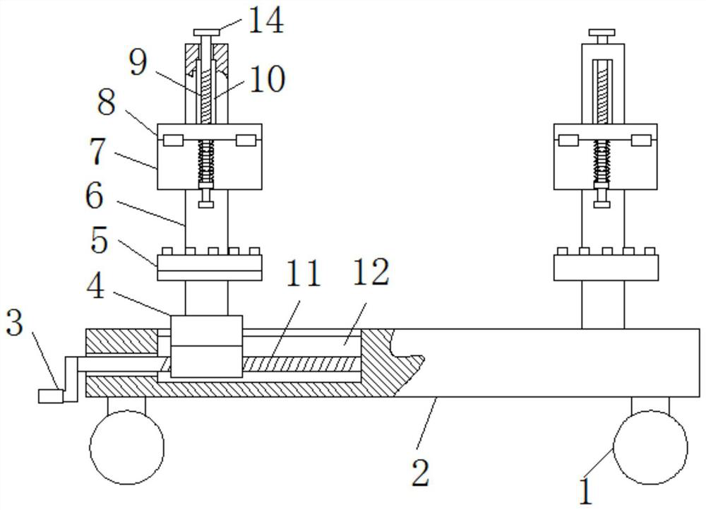
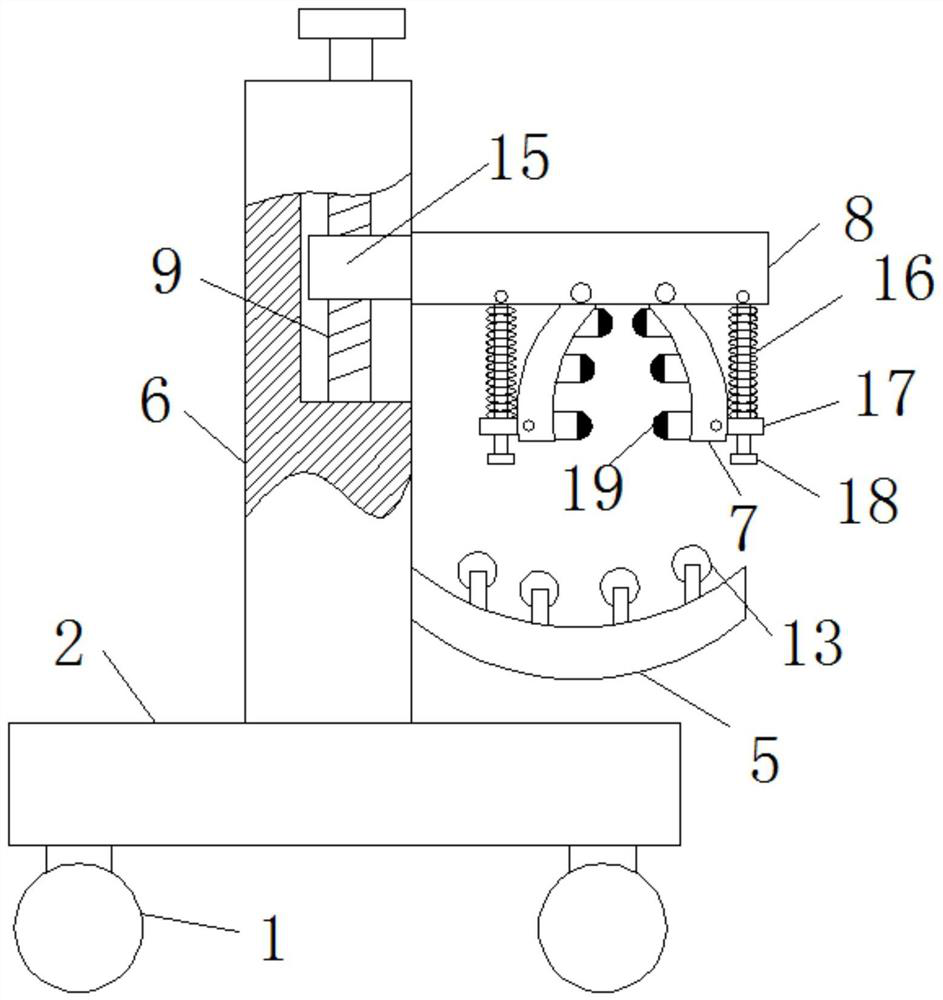
The invention discloses a circular stainless steel common plate flange wind pipe welding connection mechanism. The mechanism comprises a support plate; two support columns are arranged at the upper end of the support plate; chutes are vertically formed in the upper sides of the front ends of the two support columns; first lead screws are vertically and rotationally connected into the chutes through rolling bearings; the upper ends of the first lead screws penetrate through the rolling bearings, and are fixedly connected with turntable discs; thread sleeves are in threaded connection to the rodwalls of the first leas screws; one sides of the thread sleeves are fixedly connected with transverse plates; the lower ends of the transverse plates are hinged with two clamping plates with arc structures through hinges; multiple universal balls, uniformly distributed, are fixedly connected to one opposite sides of the two clamping plates; and the lower sides of the ends, far from the universalballs, of the clamping plates are rotationally connected with sleeves through shaft pins. The mechanism is convenient for workers to quickly join welding lines and to rotationally weld wind pipes, accelerates the welding speed, meanwhile, can counteract a certain welding stress, and improves the welding quality.

Description

technical field [0001] The invention relates to the technical field of common-plate flange welding, in particular to a circular stainless steel common-plate flange air duct welding connection mechanism. Background technique [0002] The common plate flange is mainly connected by corner codes, flange clamps, and flanges integrally connected with the air duct. Although the cost of this form of air duct is low (reducing the amount of angle steel and the labor required for making angle steel flanges), But the actual application is not as strong as the angle steel flange, and the air leakage is also large, and it must be processed by machine tools. It is almost impossible to make it by hand. It is usually only used in fresh air systems, air conditioning systems, etc., and the smoke exhaust system often uses angle steel. Flange-connected air ducts. However, civil air defense projects are absolutely not allowed to use a common plate flange connection. [0003] In the prior art, w...

Claims


Application Information

Patent Timeline
Patent Type & Authority Patents(China)
IPC IPC(8): B23K37/04B23K37/047
CPCB23K37/0443B23K37/047
Inventor 王方林岳崇华聂太富钟小龙马小丰
Owner 中创博瑞建设工程有限公司
Learn More