
Jig device for vertical closure between large mechanical tower drum and flange

A large-scale machinery and tower technology, applied in auxiliary devices, auxiliary welding equipment, welding/cutting auxiliary equipment, etc., can solve the problems of inconvenient transportation, low work efficiency, large volume of large-scale machinery towers and flanges, etc. The effect of connection stability, improving work efficiency, and facilitating transportation and maintenance

Inactive Publication Date: 2018-11-16
NANTONG ZHONGLV GEAR CO LTD
View PDF0 Cites 0 Cited by
  • Summary
  • Abstract
  • Description
  • Claims
  • Application Information

AI Technical Summary

Problems solved by technology

[0002] When the flange is installed on the traditional large-scale mechanical tower, the flange is placed on the roller frame for horizontal welding installation. As the diameter of the tower becomes larger and larger, the permanent deformation caused by the self-weight during the construction process becomes more and more serious. At the same time, the welding deformation and inclination value of the large-diameter tower flange are becoming more and more prominent. It is difficult to meet the requirements of the owner for the flatness, ellipticity and inclination value of the flange after welding. Therefore, how to solve the above problems is to ensure that the tower The key to the construction quality of the tube. At present, in order to solve this problem, the installation method of vertically closing the tower tube and the flange is proposed. When the vertical direction of the tower tube and the flange is closed, a tire frame device for the flange is required.
[0003] The existing tire frame device for vertically closing the large-scale mechanical tower and the flange is composed of a plurality of base groups in a circular structure. The flange is placed above the base group. Since the diameters of the flange and the tower are different, each When placing the flange for the first time, it is necessary to change the position of the base group to meet the needs of flanges and towers with different diameters, and when changing the position of the tire frame device, it is impossible to ensure that multiple tire frame devices form a circular structure, which is time-consuming and labor-intensive , the work efficiency is low, due to the large volume of the large mechanical tower and the flange, there is a certain inconvenience during welding or transportation after welding

Method used


Image

  • Jig device for vertical closure between large mechanical tower drum and flange
  • Jig device for vertical closure between large mechanical tower drum and flange
  • Jig device for vertical closure between large mechanical tower drum and flange

Examples


Embodiment Construction

[0021] In order to deepen the understanding of the present invention, the present invention will be further described below in conjunction with the embodiments and accompanying drawings. The embodiments are only used to explain the present invention and do not constitute a limitation to the protection scope of the present invention.

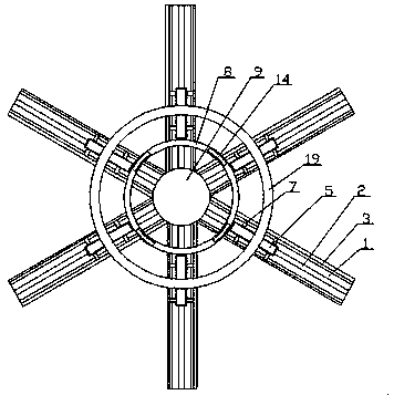
[0022] In this embodiment, a tire frame device for vertically closing a large mechanical tower tube and a flange, such as figure 1 shown, including

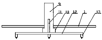
[0023] A track mechanism, such as figure 2 , image 3 As shown, the track mechanism includes a plurality of evenly arranged tracks 1, the center of the upper end surface of the track 1 is provided with a first groove 2 arranged along the extending direction of the track 1, and the cross section of the first groove 2 is a C-shaped structure The upper end surface of the track 1 is respectively placed on both sides of the first groove 2 to be provided with a second groove 3 which is consistent with ...


PUM


Abstract

The invention relates to a jig device for vertical closure between a large mechanical tower drum and a flange. The device includes a rail mechanism, which comprises several rails arranged evenly, first grooves, which are formed along the extending directions of the rails, are formed on the upper end surfaces of the rails, second grooves are formed on both sides of the upper end surfaces of the rails placed in the first grooves, and rail movement groups are formed at the center of the several rails; a base mechanism, which comprises base groups placed on the rails, the base groups comprise bases and support seats, the lower ends of the bases are bumps clamped with first grooves, support bars are arranged on both sides of the support seats, the lower ends of the support bars are clamped insecond grooves; and a stretching mechanism, which comprises several arcs connected to form a circular structure, the two adjacent arcs are connected through stretching groups in the active manner. According to the invention, the jig device has the advantages of convenient transportation, satisfying the closure of the tower drum of different diameters and the flange and improving working efficiency.

Description

Technical field: [0001] The invention relates to a tire frame device for vertically closing a large mechanical tower tube and a flange. Background technique: [0002] When the flange is installed on the traditional large-scale mechanical tower, the flange is placed on the roller frame for horizontal welding installation. As the diameter of the tower becomes larger and larger, the permanent deformation caused by the self-weight during the construction process becomes more and more serious. At the same time, the welding deformation and inclination value of the large-diameter tower flange are becoming more and more prominent. It is difficult to meet the requirements of the owner for the flatness, ellipticity and inclination value of the flange after welding. Therefore, how to solve the above problems is to ensure that the tower The key to the construction quality of the tube. At present, in order to solve this problem, the installation method of vertically closing the tower tub...

Claims


Application Information

Patent Timeline
IPC IPC(8): B23K37/053
CPCB23K37/053
Inventor 潘志进
Owner NANTONG ZHONGLV GEAR CO LTD
Learn More