
Stirring knife for stabilized soil mixing plant

A technology for stabilizing soil and mixing knives, which is applied in the field of components, can solve the problems of high impact force on the blade end face, low mixing efficiency, abnormal vibration and other problems, and achieve the effects of not easy to break, reduce energy consumption, reduce vibration and noise

Inactive Publication Date: 2018-11-16
XUZHOU XCMG MAINTENANCE MACHINERY CO LTD
View PDF8 Cites 0 Cited by
  • Summary
  • Abstract
  • Description
  • Claims
  • Application Information

AI Technical Summary

Problems solved by technology

[0003] The end face of the existing mixing knife has no inclination angle, no jagged concave-convex cavity, and due to the collision between the stirring and the material, the impact force on the end face of the blade during stirring is large, and the material is pressed harder and harder, and the blade wears seriously. Abnormal vibration and noise, the stirring efficiency is greatly reduced, which brings great problems to the use

Method used


Image

  • Stirring knife for stabilized soil mixing plant
  • Stirring knife for stabilized soil mixing plant
  • Stirring knife for stabilized soil mixing plant

Examples


Embodiment Construction

[0019] In order to make the object, technical solution and advantages of the present invention clearer, the present invention will be further described in detail below. However, it should be understood that the specific embodiments described here are only used to explain the present invention, and are not intended to limit the scope of the present invention.

[0020] Unless otherwise defined, all technical terms and scientific terms used herein have the same meaning as commonly understood by those skilled in the technical field of the present invention, and the terms used in the description of the present invention herein are only to describe specific implementations The purpose of the example is not intended to limit the present invention.

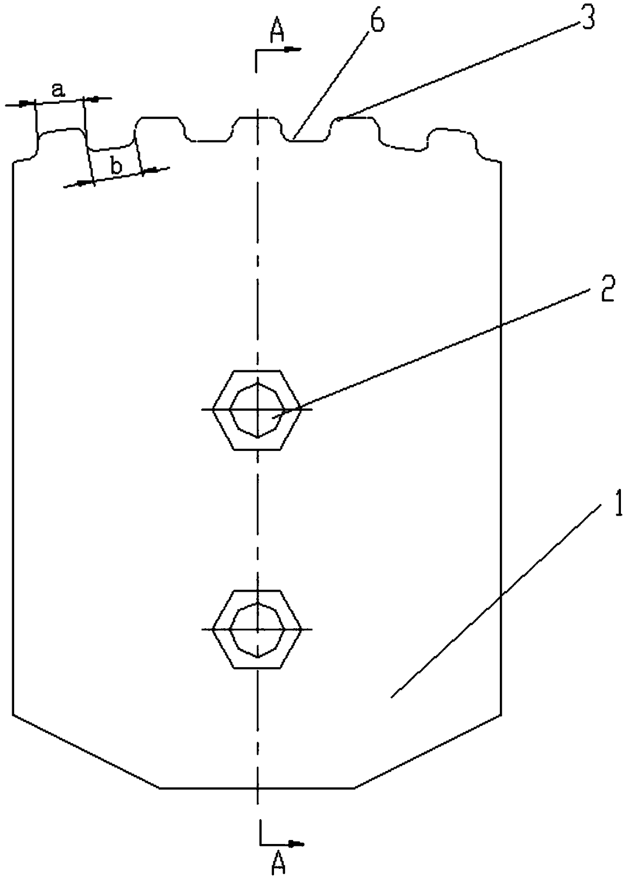
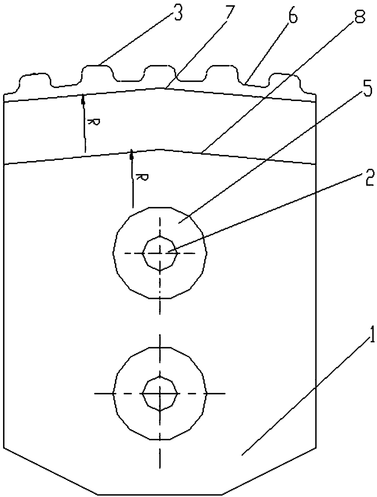
[0021] like figure 1 , figure 2 and image 3 As shown, a mixing knife for stabilized soil plant mixing equipment includes a blade body 1, and the blade body 1 is provided with a mounting hole 2 fixed with the stirring arm, and also in...


PUM


Abstract

The invention discloses a stirring knife for a stabilized soil mixing plant. The stirring knife comprises a knife blade body which is provided with mounting holes fixed with a stirring arm; the stirring knife also comprises bosses arranged on the knife blade body, and a knife blade end arranged at one side of the knife blade body; each boss is located at one side of one mounting hole; the knife blade end is connected with the knife blade body in a circular arc transition manner; the knife blade end is provided with a jagged concave-convex cavity which comprises convex parts and concave parts that are alternately arranged; and a cutting angle beta is formed between the knife blade end and a horizontal plane. The stirring knife provided by the invention has simple structure; the surface of the knife blade end is designed to have a cutting angle with similar to a cutting tool and the jagged concave-convex cavity is arranged at the same time, so a discharge groove is formed during blending, and thus, the direct collision force between the surface of the knife blade end and a material is retarded during stirring, vibration and noise during stirring operation are reduced, and energy consumption is decreased.

Description

technical field [0001] The invention relates to a component used in a mixer of stabilized soil mixing equipment, in particular to a mixing knife for stabilized soil mixing equipment. Background technique [0002] The mixer is the core component of the stabilized soil plant mixing equipment, and it undertakes the function of mixing various stones, sand, stone powder and other aggregates for the stabilized soil plant mixing equipment. The main part of the mixer includes the main body of the mixer, the bearing seat, the shaft end plate, the mixing shaft, the mixing knife, the bearing, the motor, the reducer, the gear and other parts. Most of the mixing knives are made of metal, and the stabilized soil factory mixing Equipment mixing knife mixing is similar to the principle of tool cutting, so the mixing knife must also have appropriate geometric parameters such as cutting angle. [0003] The end face of the existing mixing knife has no inclination angle, no jagged concave-conv...

Claims


Application Information

Patent Timeline
Patent Type & Authority Applications(China)
IPC IPC(8): B28C5/08
Inventor 卢敏陈言国樊右文袁刚强
Owner XUZHOU XCMG MAINTENANCE MACHINERY CO LTD
Learn More