A car radiator cleaning device with automatic cleaning ability

A car radiator and automatic cleaning technology, which is applied in vehicle cleaning, vehicle maintenance, transportation and packaging, etc., can solve problems such as easy dust entry, increased dust falling surface, troublesome cleaning, etc., to achieve rapid and comprehensive cleaning and save space structure, to avoid the effect of dust accumulation

Active Publication Date: 2020-03-27
亳州易泽信息科技有限公司
View PDF5 Cites 0 Cited by
  • Summary
  • Abstract
  • Description
  • Claims
  • Application Information

AI Technical Summary

Problems solved by technology

[0004] (1) The car radiator is used to dissipate the heat of the generator. It is used frequently, and the car radiator is installed at the front of the car. It is often in contact with the ground at a close distance, and it is easy for dust to enter. The existing cleaning device is dissipating heat. It is necessary to stop the fan when cleaning the engine, which causes idling during driving and damages the engine. The non-stop cleaning device will evaporate water vapor to the parts of the car body, making the parts of the car body more likely to stick. Attach dust, thereby accelerating the natural oxidation speed of the body;
[0005] (2) Moreover, the chip of the heat dissipation belt is inside the car radiator, and there are many heat dissipation main pipes, and the fins increase the dust falling surface accordingly, and the heat dissipation effect of the radiator with more dust is reduced, causing damage to the engine, and It is more troublesome to clean, and it is not easy to clean;
[0006] (3) The existing external cleaning device can only be washed by simple one-way high pressure, and the excessively high impact water flow will easily cause the deformation of the radiator tube at the impact point, and at the same time, the radiating surface of the washing is small, and it is impossible to completely wash the whole

Method used


Image

  • A car radiator cleaning device with automatic cleaning ability
  • A car radiator cleaning device with automatic cleaning ability
  • A car radiator cleaning device with automatic cleaning ability

Examples


Embodiment Construction

[0026] The following will clearly and completely describe the technical solutions in the embodiments of the present invention with reference to the accompanying drawings in the embodiments of the present invention. Obviously, the described embodiments are only some, not all, embodiments of the present invention. Based on the embodiments of the present invention, all other embodiments obtained by persons of ordinary skill in the art without making creative efforts belong to the protection scope of the present invention.

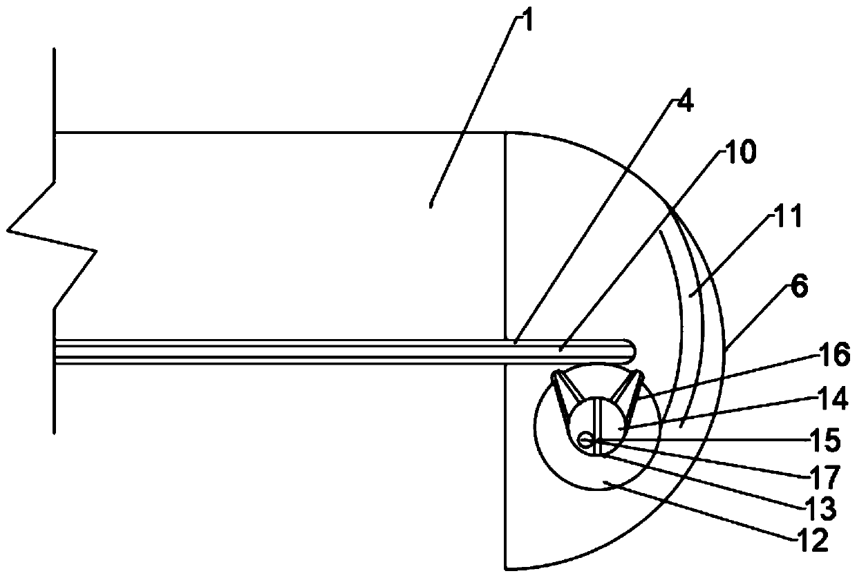
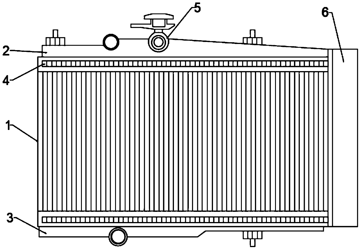
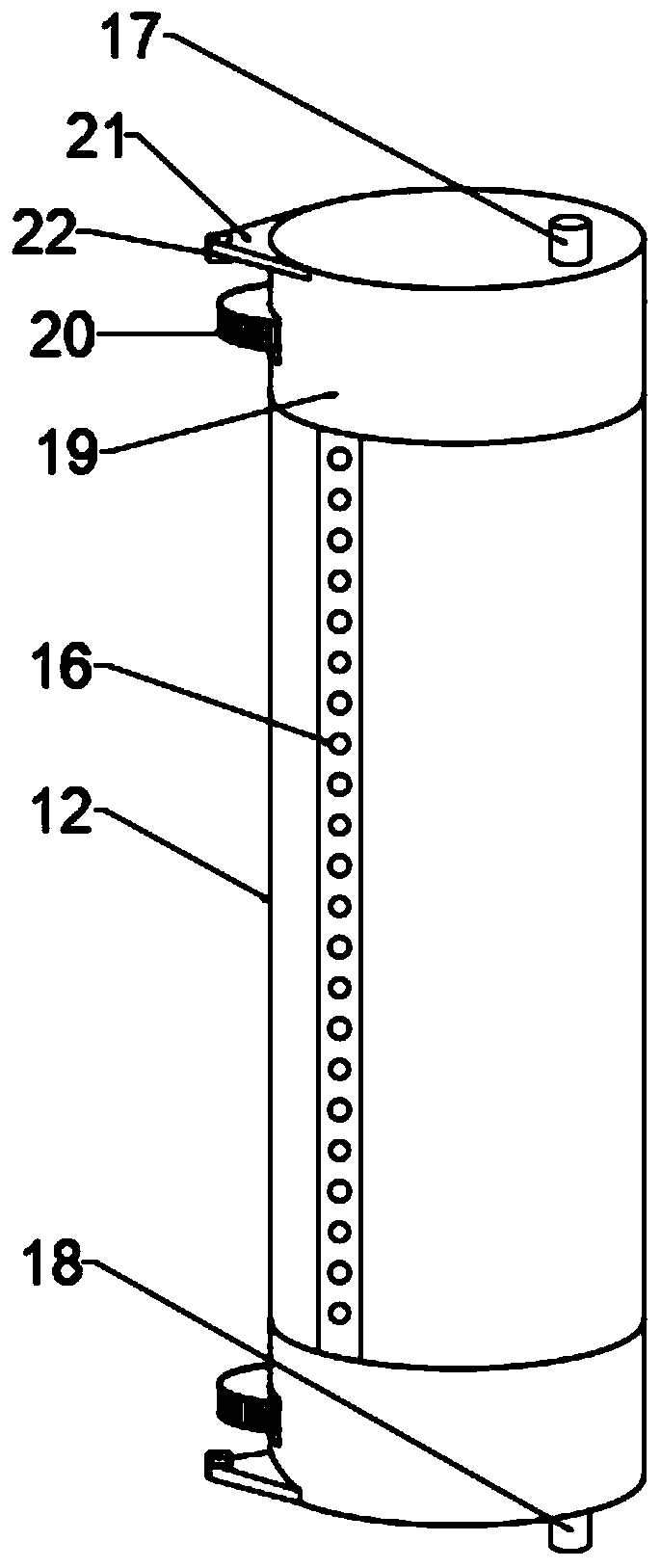
[0027] Such as figure 1 , figure 2 , image 3 and Figure 4 As shown, the present invention provides a car radiator cleaning device with automatic cleaning capability, comprising a main body 1, the top and bottom of the main body 1 are respectively provided with an upper water cover 2 and a lower water cover 3, and the upper water cover 2 A three-way valve 5 is arranged in the middle of the top, and a fan cover 7 is arranged on the back side of the main bo...


PUM


Abstract

The invention discloses an automobile radiator cleaning device with an automatic cleaning capacity. The automobile radiator cleaning device with the automatic cleaning capacity comprises a main body;an upper water shield and a lower water shield are correspondingly arranged at the top and the bottom of the main body; a three-way valve is arranged in the middle of the top of the upper water shield; a fan cover is arranged on the back side of the main body; displacement rails are arranged at the top and the bottom of the front side surface of the main body; clamping grooves are formed in the tops of the displacement rails; a cleaning cover is arranged at the side edge of the main body; an inner column is arranged in the cleaning cover; motor chambers are formed in the top and the bottom ofthe inner column; transmission wheels and triangular plates are embedded in the side surfaces of the motor chambers; interactive shafts are mounted on the triangular plates; sliding shafts are connected with the displacement rails through the clamping grooves; a water air pipe is arranged in the inner column; the interior of the water air pipe is partitioned into an air chamber and a water chamberthrough a middle partition plate; nozzles which are symmetric to each other relative to the middle partition plate are formed in the air chamber and the water chamber; the nozzles extend to the surface of the inner column; and arc guiding pipes are arranged at the top and the bottom of the cleaning cover. Comprehensive no-dead-angle flushing is realized.

Description

technical field [0001] The invention relates to the technical field of automobile radiators, in particular to an automobile radiator cleaning device with automatic cleaning capability. Background technique [0002] Automobile radiator is an indispensable and important part in the cooling system of automobile water-cooled engine, and it is developing in the direction of light weight, high efficiency and economy. The structure of automobile radiators is also constantly adapting to new developments. The core of tube-fin radiators is composed of many thin cooling tubes and cooling fins. Most of the cooling tubes use oblate cross-sections to reduce air resistance and increase heat transfer area; The core should have enough flow area to allow the coolant to pass through, and it should also have enough air flow area to allow enough air to pass through to take away the heat from the coolant to the radiator. At the same time, it must have enough heat dissipation area to complete the...

Claims


Application Information

Patent Timeline
Patent Type & Authority Patents(China)
IPC IPC(8): B60S1/64
CPCB60S1/64
Inventor 张阳
Owner 亳州易泽信息科技有限公司
Why Eureka
Try Eureka