Body longitudinal beam and auxiliary frame mounting structure

A sub-frame and longitudinal beam technology, applied in the field of car body, can solve the problems of material performance decline, poor fatigue resistance, thermal cracks, etc., and achieve the effects of low cost, improved torsion resistance, and simple production method.

Active Publication Date: 2018-11-16
CHONGQING CHANGAN AUTOMOBILE CO LTD
View PDF5 Cites 3 Cited by
  • Summary
  • Abstract
  • Description
  • Claims
  • Application Information

AI Technical Summary

Problems solved by technology

However, due to the differences in welding welding levels, some welded welding thread sleeve structures are prone to problems such as pores and heat cracks, which will directly lead to a significant decline in material performance and poor fatigue tolerance.

Method used


Image

  • Body longitudinal beam and auxiliary frame mounting structure
  • Body longitudinal beam and auxiliary frame mounting structure
  • Body longitudinal beam and auxiliary frame mounting structure

Examples


Embodiment Construction

[0025] The present invention will be further described below in conjunction with accompanying drawing.

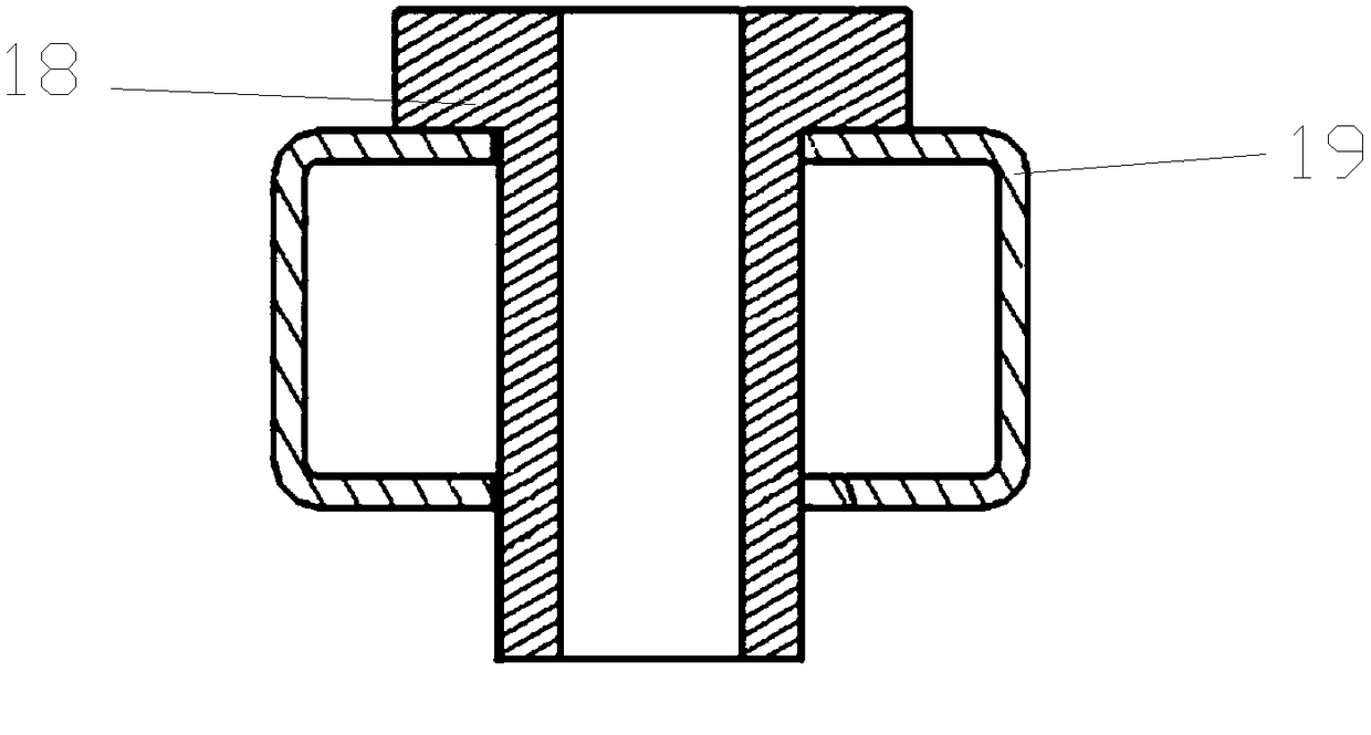
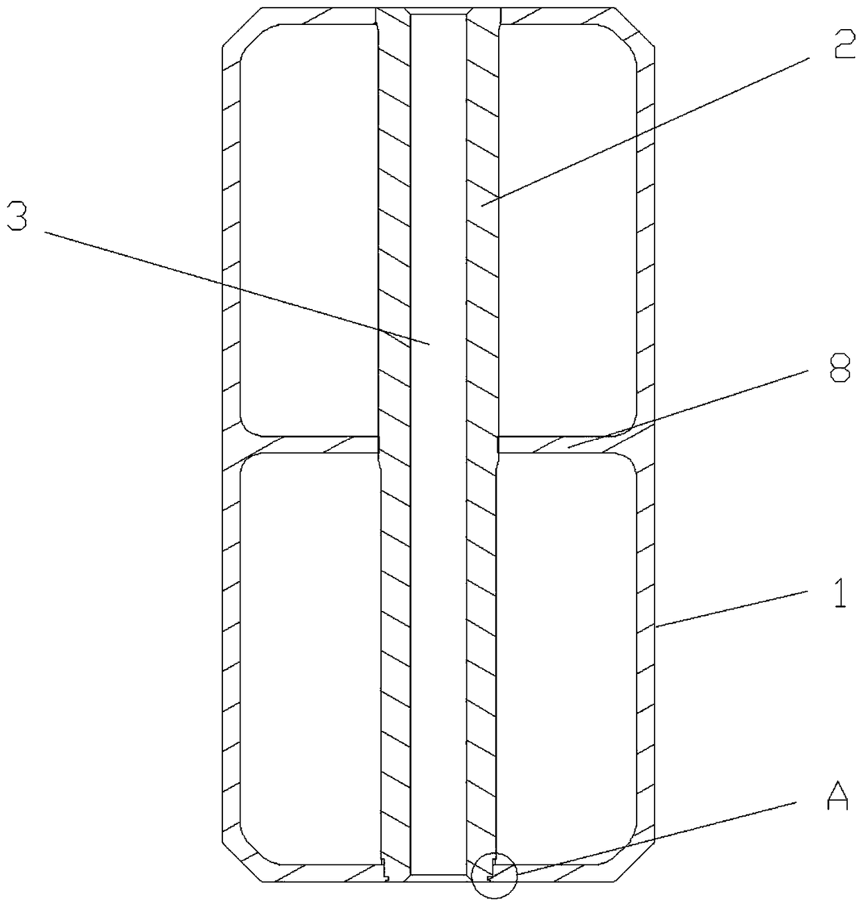
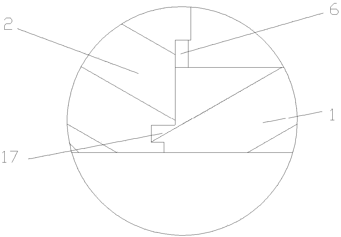
[0026] Such as figure 2 A vehicle body side beam, comprising a body side beam body 1 with a cross-section in the shape of a "mouth" and a fixing part 2 arranged in the body side beam body 1. The bottom surface of 2 is provided with the screw hole 3 that is used for installing subframe; Figure 4 As shown, the bottom plate of the longitudinal beam body 1 of the vehicle body is provided with a first through hole 4 corresponding to the fixing part 2, and the fixing part 2 includes a first rod segment for matching with the first through hole 4, and the first rod segment The outer wall is provided with an extruded part protruding outward, such as image 3 with Figure 8 As shown, the outer wall of the first rod section is provided with a recessed part 5 facing the hole wall of the first through hole 4, and the bottom plate of the body side member body 1 is provided with an e...


PUM


Abstract

The invention relates to a body longitudinal beam which comprises a body longitudinal beam body and a fixed part arranged in the body longitudinal beam body. The fixed part is integrally in the shapeof a rod, a threaded hole is formed in the bottom of the fixed part, a first through hole is formed in a bottom plate of the body longitudinal beam body, the fixed part comprises a first rod section matched with the first through hole, an outward projecting extrusion portion is arranged on the outer wall of the first rod section, a recess is arranged on the outer wall of the first rod section, andthe bottom plate of the body longitudinal beam body is provided with a groove formed by extruding the bottom plate of the body longitudinal beam body by the extrusion portion along the axis directionof the first rod section, the wall of the first through hole is provided with a squeezing-out portion which is formed by extruding the bottom plate of the body longitudinal beam body by the extrusionportion along the axis direction of the first rod section and expands into the recess, the extrusion portion and the groove are jogged, and the squeezing-out portion is embedded into the recess, so that the fixed part is fixed into the body longitudinal beam body. The fatigue resistance of a mounting port of an existing body for mounting an auxiliary frame can be improved. The invention further provides an auxiliary frame mounting structure.

Description

technical field [0001] The invention relates to a vehicle body, in particular to a vehicle body longitudinal beam and an auxiliary frame installation structure. Background technique [0002] Most of the body structures of today's cars are made of aluminum alloy materials. The body structure made of aluminum alloy includes mounting points for installing sub-frames. Due to the high requirements for the strength of the sub-frame and its mounting points, the whole vehicle , and generally the installation point for installing the subframe is set on the longitudinal beam of the engine compartment. Therefore, the requirements for the strength of the installation point of the subframe on the longitudinal beam of the engine compartment are relatively high, and the high-strength installation point has a high performance, especially NVH performance, is very important. In the past, the installation point of the sub-frame used a welded threaded sleeve structure for the longitudinal beam...

Claims


Application Information

Patent Timeline
Patent Type & Authority Applications(China)
IPC IPC(8): B62D27/02B62D21/00B62D21/04
CPCB62D21/00B62D21/04B62D27/023
Inventor 孟吉登
Owner CHONGQING CHANGAN AUTOMOBILE CO LTD
Why Eureka
Try Eureka