Tilting type vertical take-off and landing fixed-wing unmanned aerial vehicle and flight control system

A flight control system, vertical take-off and landing technology, applied in the field of UAV and flight control system, can solve the problems of increased aerodynamic resistance, long acceleration time, failure of mode conversion, etc., to ensure synchronization, simple structure, and stable heading Effect

Inactive Publication Date: 2018-11-16
哈尔滨埃珀司智能装备技术有限公司
View PDF12 Cites 10 Cited by
  • Summary
  • Abstract
  • Description
  • Claims
  • Application Information

AI Technical Summary

Problems solved by technology

The flight time and flight distance of fixed-wing UAVs are greatly improved compared with ordinary multi-rotor UAVs, but their take-off and landing processes are limited by the runway, and their maneuverability and adaptability to the environment are far inferior to those of UAVs. The multi-rotor structure UAV is lower
[0003] At present, the UAV control system of this configuration is mainly aimed at some aircraft with a small weight (less than 20kg). There will be issues with attitude instability, altitude loss, and excessive acceleration times, resulting in failed mode transitions
[0004] At the same time, in order to ensure the synchronization of the tilting of the two power motors at the front end when the multi-rotor structure and the fixed wing perform mode conversion, the current method used is: the installation axis of the rotor structure motors at the front and rear ends is perpendicular to the longitudinal axis of the fuselage, and the two front motors tilt together, which increases aerodynamic drag as the aircraft accelerates forward
[0005] At present, the driving device for the tilting of the rotor structure motor is driven by the steering gear. Since the steering gear can only complete the position locking under the condition of power supply, the steering gear is always in the flight process regardless of the rotor structure mode or the fixed wing mode. It works with electricity, this way will reduce the battery life

Method used


Image

  • Tilting type vertical take-off and landing fixed-wing unmanned aerial vehicle and flight control system
  • Tilting type vertical take-off and landing fixed-wing unmanned aerial vehicle and flight control system
  • Tilting type vertical take-off and landing fixed-wing unmanned aerial vehicle and flight control system

Examples


Embodiment Construction

[0028] The technical solutions in the embodiments of the present invention will be described in detail below in conjunction with the accompanying drawings in the embodiments of the present invention, and relevant user operations in the implementation of the present invention fall within the scope of protection of this patent.

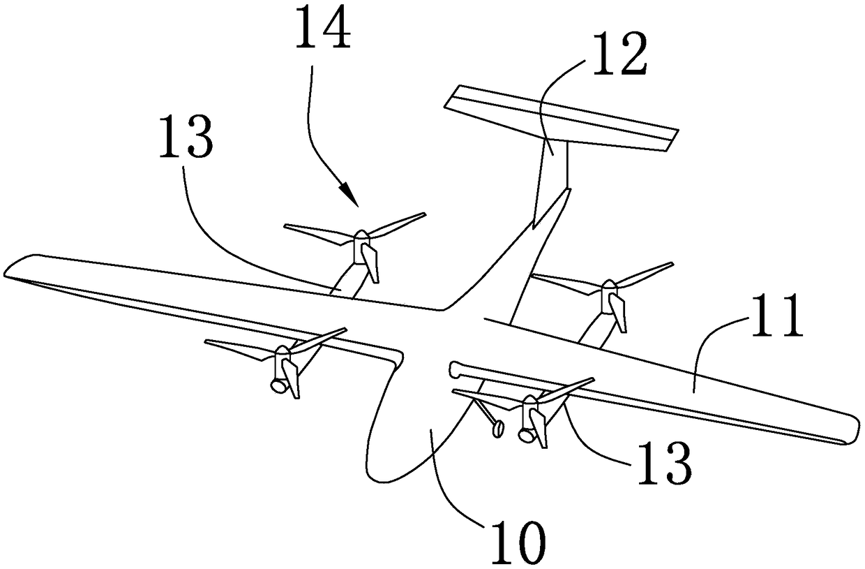
[0029] see figure 1 , the tilting vertical take-off and landing fixed-wing unmanned aerial vehicle provided by the present invention comprises a fuselage 10, a wing 11, an empennage 12, two support arms 13 and four rotor structures 14.

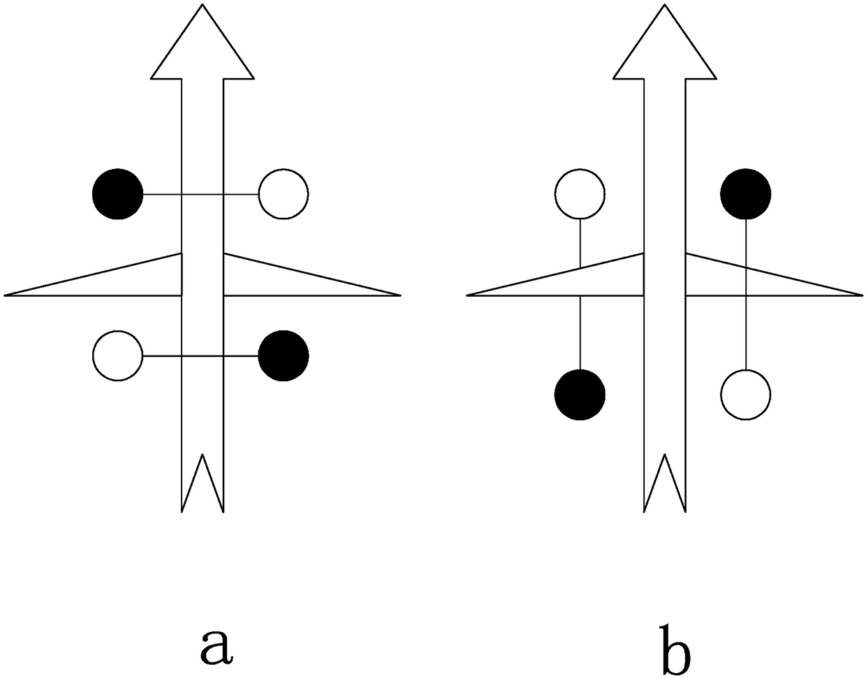
[0030] It should be noted that the fuselage 10 and the wing 11 are of a fixed-wing aircraft layout. Moreover, the two support arms 13 are installed on the fuselage 10 or the wing 11 along the extending direction parallel to the fuselage 10, so that each support arm 13 is formed with The front and rear of the front and rear sides. compared to if figure 2 In the traditional front-to-back installation method shown in a...


PUM


Abstract

The invention provides a tilting type vertical take-off and landing fixed-wing unmanned aerial vehicle and a flight control system. The tilting type vertical take-off and landing fixed-wing unmanned aerial vehicle comprises an unmanned aerial vehicle body, wings and a tail fin; the unmanned aerial vehicle body and the wings are in the form of a fixed-wing aircraft layout; the tilting type verticaltake-off and landing fixed-wing unmanned aerial vehicle comprises two supporting arms and four rotor structures; the two supporting arms are mounted on the unmanned aerial vehicle body or the wings in a direction parallel to the unmanned aerial vehicle extending direction so that a front end and a rear end distributed on the front and rear sides of the wing are formed on each supporting arm; therotor structures are correspondingly mounted at the front end and the rear end of each supporting arm; the geometric centers of the four rotor structures are coincided with the gravity center of the whole unmanned aerial vehicle; and the four rotor structures can all adjust their tilting angles so as to form a tilting power device of the unmanned aerial vehicle. The invention further provides theflight control system based on the tilting type vertical take-off and landing fixed-wing unmanned aerial vehicle.

Description

technical field [0001] The invention relates to the technical field of unmanned aerial vehicles, in particular to a tilting vertical take-off and landing fixed-wing unmanned aerial vehicle and a flight control system. Background technique [0002] With the development of drone technology in recent years, drones have achieved considerable application results in many fields. However, due to the growth of application requirements and the expansion of application scope, multi-rotor UAVs have gradually exposed the defects of short endurance time. Under the urgent application demand, people began to study the unmanned aerial vehicles with longer battery life and longer flight distance—fixed-wing drones. The flight time and flight distance of fixed-wing UAVs are greatly improved compared with ordinary multi-rotor UAVs, but their take-off and landing processes are limited by the runway, and their maneuverability and adaptability to the environment are far inferior to those of UAVs....

Claims


Application Information

Patent Timeline
Patent Type & Authority Applications(China)
IPC IPC(8): B64C27/28B64C27/26B64C19/02
CPCB64C19/02B64C27/26B64C27/28B64U10/25B64U70/80B64U10/10B64U30/20B64U50/13
Inventor 吴雄林
Owner 哈尔滨埃珀司智能装备技术有限公司
Why Eureka
Try Eureka