Pipe fitting reversing and feeding mechanism

A technology of reversing mechanism and pipe fittings is applied in the field of workpiece processing and conveying machinery and equipment, and the continuous production and processing of pipe fittings. Effect

Inactive Publication Date: 2018-11-16
嘉兴汉羿文化传播有限公司
View PDF0 Cites 20 Cited by
  • Summary
  • Abstract
  • Description
  • Claims
  • Application Information

AI Technical Summary

Problems solved by technology

During the production and processing of pipe fittings, it is necessary to sequentially load the pipe fittings that have been processed in the previous process to enable the processing of the subsequent process. After the existing pipe fittings have been processed in the previous process, in order to continue to process the pipe Production and processing, the existing method is to manually feed the pipe fittings one by one, the labor intensity of the workers is high, and the feeding efficiency of the pipe fittings is low, making it difficult to meet the needs of large-scale pipe fitting production and processing. It is difficult to adjust the processing position of the pipe fittings during the transfer and transfer process of the pipe fittings in turn. The existing pipe fitting station adjustment mainly uses the manipulator to grab and adjust the pipe fittings, but the manipulator is used for position adjustment. , first of all, it is necessary to grab the pipe fittings. In the process of grabbing the pipe fittings, the existing manipulators often cause the pipe fittings to fall off due to poor grasping during the process of grabbing the pipe fittings, resulting in the pipe fittings not being able to be processed normally. The processing of the process makes the efficiency and quality of pipe fittings processing not guaranteed, and in the process of using the manipulator to grab the pipe fittings, the manipulator needs multiple driving mechanisms to drive continuously and independently, the driving energy consumption is high, and multiple driving mechanisms It is also very prone to failure, it is difficult to run stably for a long period of time, and it cannot guarantee that the pipe fittings can be stably grabbed and placed one by one to the required station continuously and efficiently, making it difficult for the pipe fittings to be processed efficiently and accurately
The existing pipe fittings are mainly conveyed by material pipes during the conveying process, and it is difficult to block the pipe fittings during the sliding process when conveyed by the material pipes, which makes it difficult to realize the rolling and unloading of the pipe fittings one by one, and it is difficult to transfer the pipe fittings during the transfer process. Efficient and stable vertical flipping of pipe fittings accurately makes it difficult to adjust the position of pipe fittings conveniently and accurately. During the loading process of existing pipe fittings, it is difficult to reverse the conveying direction of pipe fittings conveniently and efficiently, which makes it difficult to meet the requirements due to space Restriction requires two material pipes to transfer and reverse the pipe fittings, which reduces the convenience of pipe fittings transfer and processing, and cannot meet the needs of processing and use

Method used


Image

  • Pipe fitting reversing and feeding mechanism
  • Pipe fitting reversing and feeding mechanism
  • Pipe fitting reversing and feeding mechanism

Examples


Embodiment Construction

[0017] In order to further describe the present invention, a specific implementation of a pipe reversing and feeding mechanism will be further described below in conjunction with the accompanying drawings. The following examples are explanations of the present invention and the present invention is not limited to the following examples.

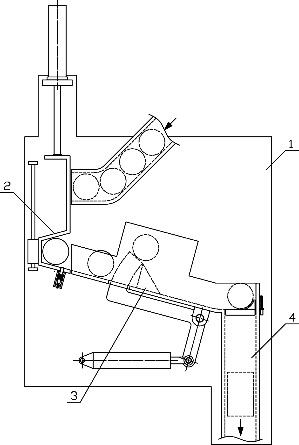
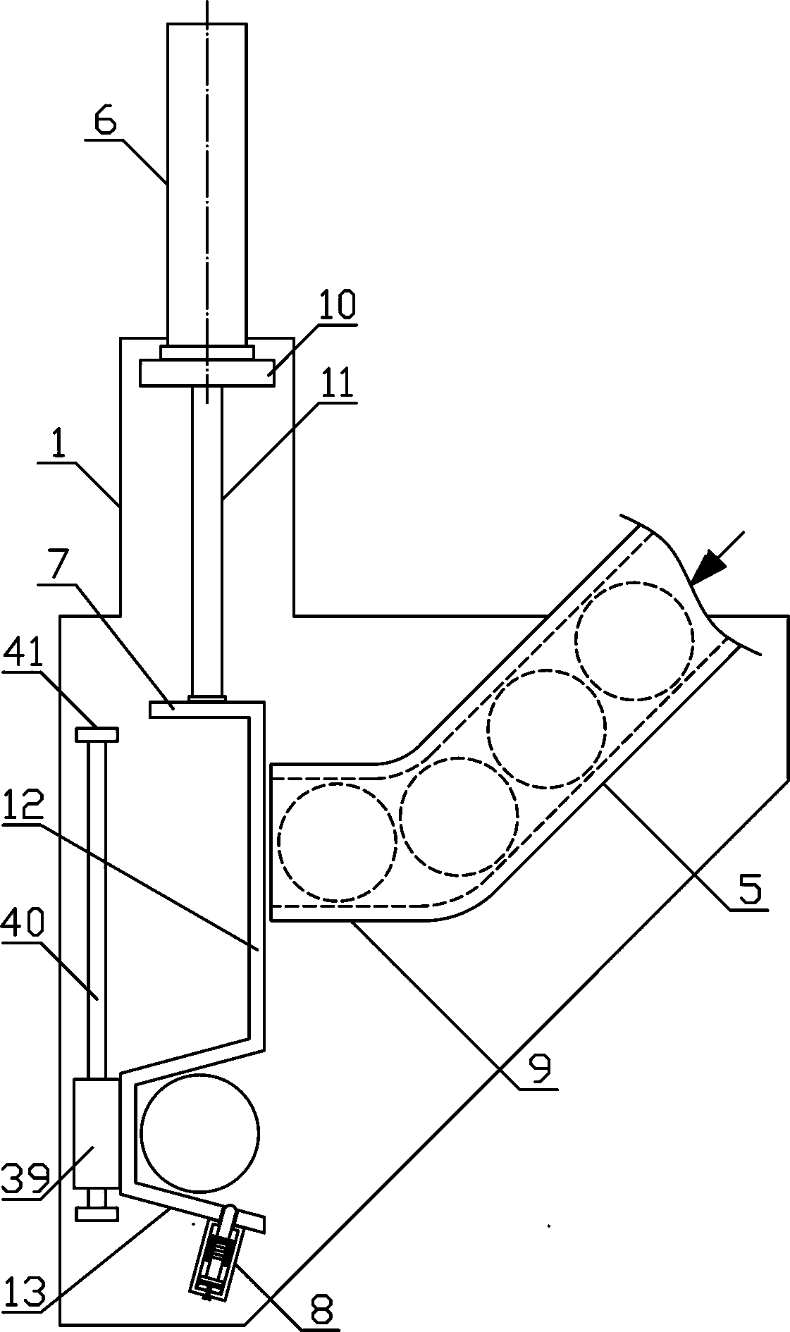
[0018] Such as figure 1 As shown, a pipe reversing feeding mechanism of the present invention includes a fixed bracket 1, a reversing mechanism 2, a conduit mechanism 3 and a turning mechanism 4, the reversing mechanism 2 is vertically arranged on the side above the fixed bracket 1, and the conduit mechanism 3 is inclined It is arranged downwards on the fixed bracket 1 on the lower side of the reversing mechanism 2 , and the turning mechanism 4 is vertically arranged on the fixed bracket 1 on the lower side of the conduit mechanism 3 . Such as figure 2 As shown, the reversing mechanism 2 of the present invention includes a conduit material ...


PUM


Abstract

The invention discloses a pipe fitting reversing and feeding mechanism, and belongs to the field of workpiece machining and conveying mechanical equipment. A reversing mechanism is vertically disposedon one side of the upper portion of a fixed bracket, and a pipe-guiding mechanism is obliquely and downwardly disposed on the fixed bracket on the lower side of the reversing mechanism; a turnover mechanism is vertically disposed on the fixed bracket on the lower side of the pipe-guiding mechanism, and a pipe-discharging charge-pipe is horizontally arranged at the lower end of a pipe-guiding charge-pipe in a communicating mode; a pipe-limiting mechanism is fixedly arranged on the lower side of a pipe-placing clamping groove in inclined and upward modes, wherein the pipe-placing clamping groove is formed in the lower end of a pipe-blocking connecting plate; a pipe-blocking fixing block is fixedly and horizontally arranged in the middle of the pipe-guiding charge-pipe, and a pipe-feeding push plate of a circular arc structure is vertically arranged at the upper end of a pipe-pushing turnover plate; and the upper end of a slide downward charge-pipe communicates with the lower end of thepipe-guiding charge-pipe, and one end of a pipe-collecting turnover plate is connected to the upper side of the slide downward charge-pipe in a hinged mode. The pipe fitting reversing and feeding mechanism is reasonable in structural design, and pipe fittings can be transferred smoothly and conveniently one by one in a reversing mode, turnover is carried out accurately during the pipe fitting feeding process, thereby the automatic adjustment of pipe fitting working stations is realized, and the needs of machining and use are met.

Description

technical field [0001] The invention belongs to the field of workpiece processing and conveying machinery, in particular to a pipe fitting reversing feeding mechanism, which is mainly used in the field of continuous production and processing of pipe fittings. Background technique [0002] Pipe fittings refer to workpieces with a cylindrical structure. There are many types of pipe fittings. Different pipe fittings use different materials. The quality of the material directly determines the quality of the pipe fittings. Pipe fittings are necessary materials for construction engineering and mechanical equipment. A general term for components that play the roles of connection, control, direction change, flow diversion, sealing, support, etc. Steel pipe fittings are the most important type of pipe fittings. Steel pipe fittings are pressure-bearing pipe fittings. According to different processing techniques, steel pipe fittings can be divided into: butt welding pipe fittings, sock...

Claims


Application Information

Patent Timeline
Patent Type & Authority Applications(China)
IPC IPC(8): B65G47/248
CPCB65G47/248
Inventor 王英
Owner 嘉兴汉羿文化传播有限公司
Why Eureka
Try Eureka