Bridge type opening and closing bridge device of flat glass production line

A flat glass and production line technology, applied to lighting and heating equipment, conveyor objects, furnaces, etc., can solve the problems of unsafe hidden dangers in the flat glass connection production line, reduce product losses and unsafe hidden dangers, and reduce labor and energy cost, the effect of solving logistics problems

Inactive Publication Date: 2018-11-16
IRICO
View PDF8 Cites 4 Cited by
  • Summary
  • Abstract
  • Description
  • Claims
  • Application Information

AI Technical Summary

Problems solved by technology

[0005] Aiming at the problems existing in the prior art, the present invention provides a bridge-type opening and closing equipment for a flat glass production line, which greatly reduces labor and energy costs, reduces product losses and hidden dangers of safety, and effectively solves the problem of flat glass The logistics problems of connected production and the potential safety hazards in the production line

Method used


Image

  • Bridge type opening and closing bridge device of flat glass production line
  • Bridge type opening and closing bridge device of flat glass production line

Examples


Embodiment 1

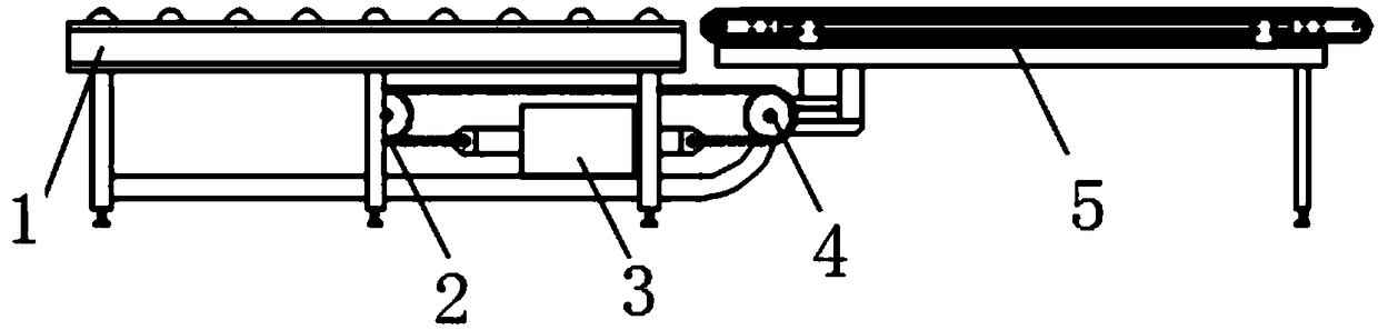
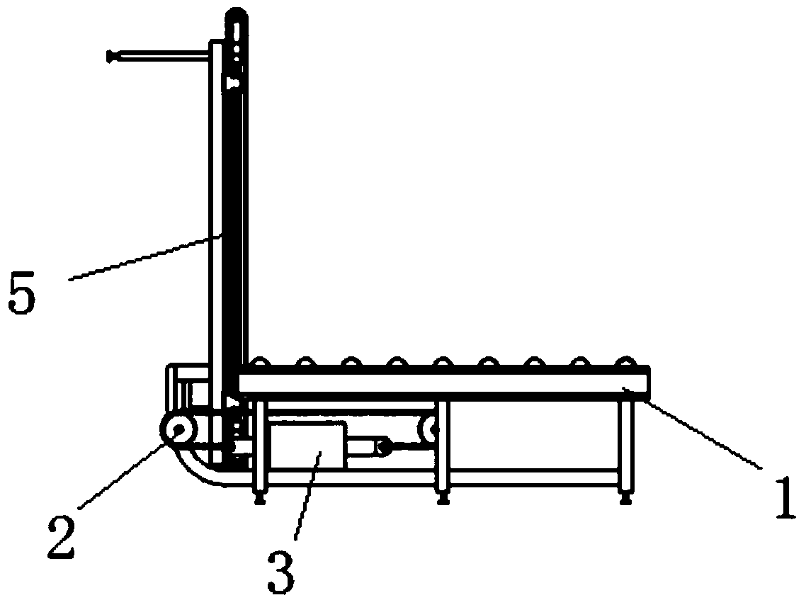
[0023] Such as figure 1 As shown, a bridge type opening and closing device for a flat glass production line includes a main conveying roller table 1, a sprocket 2, a cylinder 3, a rotating shaft 4, and a synchronous belt roller table 5.

[0024] Among them, the main conveyor roller table 1 is arranged at one end of the synchronous belt roller table 5, one end of the main conveyor roller table 1 is symmetrically provided with two support arms, and the support arms extend out of the end of the main conveyor roller table 1 and extend into the synchronous belt. In the lower part of the belt roller table 5, the rotating shaft 4 is horizontally arranged on the support arm and can be rotated freely. The bottom of the bracket of the synchronous belt roller table 5 is provided with an L-shaped bracket, and the horizontal end of the L-shaped bracket is fixedly connected with the rotating shaft 4.

[0025] The air cylinder 3 adopts a double-guide rod double-acting air cylinder. The air cylinde...

Embodiment 2

[0031] The structure of this embodiment is basically the same as that of the first embodiment, and the difference lies in the transmission mechanism, which is specifically as follows.

[0032] This embodiment adopts positive and negative motors for transmission. The motor is installed on the bracket of the main conveying roller table 1, and the end of the motor output shaft is equipped with a driving gear. The bracket of the main conveying roller table 1 is equipped with a track, which is installed in the track. There is a rack, a driven gear is installed on the rotating shaft, and the driving gear and the driven gear are matched with the rack.

[0033] The rack is provided with a stroke limit device to limit the turning angle of the synchronous belt roller table.

[0034] The starting motor rotates counterclockwise, the driving gear drives the rack to move to the right, and the rack drives the driven gear to rotate counterclockwise, thereby driving the timing belt roller to turn 90°...


PUM


Abstract

The invention discloses bridge type opening and closing bridge equipment of a flat glass production line. A flat glass main conveying roller way and a synchronous belt roller way are connected througha rotating shaft, a chain is pulled through a telescopic air cylinder arranged below the main conveying roller way, the chain drives a gear installed on the rotating shaft, and the gear rotates to drive the rotating shaft to rotate, so that the synchronous belt roller way is driven to rotate, and the horizontal and vertical 90-degree turnover of the synchronous belt roller way is realized. According to the equipment, intelligent production of the flat glass connecting line is realized, a pioneer which is produced by connecting the front end and the rear end of flat glass is opened up, the problem of product logistics at the front end and the rear end of the flat glass is solved, the loss of products in the transportation process is reduced, the labor cost caused by upper pieces and lowerpieces is greatly reduced, and benefits are brought to enterprises.

Description

Technical field [0001] The invention relates to the field of flat glass production, in particular to a bridge type opening and closing device for a flat glass production line. Background technique [0002] With the continuous progress of society, the application of flat glass is more and more extensive, and the demand is increasing. However, due to the impact of external factors such as the price increase of upstream raw materials and changes in downstream market policies, the production cost of flat glass is getting higher and higher, and the profit margin is getting smaller and smaller. Facing the severe industry situation, only by starting from internal factors, improving technical strength, optimizing production methods and purchasing advanced production equipment, can we maintain a high level of profit. [0003] In the flat glass industry, products are always transferred manually or by forklift to achieve continuous production at the front and back ends of the production line...

Claims


Application Information

Patent Timeline
Patent Type & Authority Applications(China)
IPC IPC(8): B65G49/06
CPCB65G49/063
Inventor 俞长庆侯晓宇徐伟东
Owner IRICO
Why Eureka
Try Eureka