

Electric wire rewinding and take-up machine
A wire take-up machine and electric wire technology, which is applied in the direction of conveying filamentous materials, thin material processing, transportation and packaging, etc. It can solve the problems of increasing the workload and affecting the efficiency of wire winding, so as to improve efficiency and safety , the effect of improving the quality
Patent Information
- Authority / Receiving Office
- CN · China
- Current Assignee / Owner
- Publication Date
- 2018-11-16
- Estimated Expiration
- Not applicable · inactive patent
Smart Images
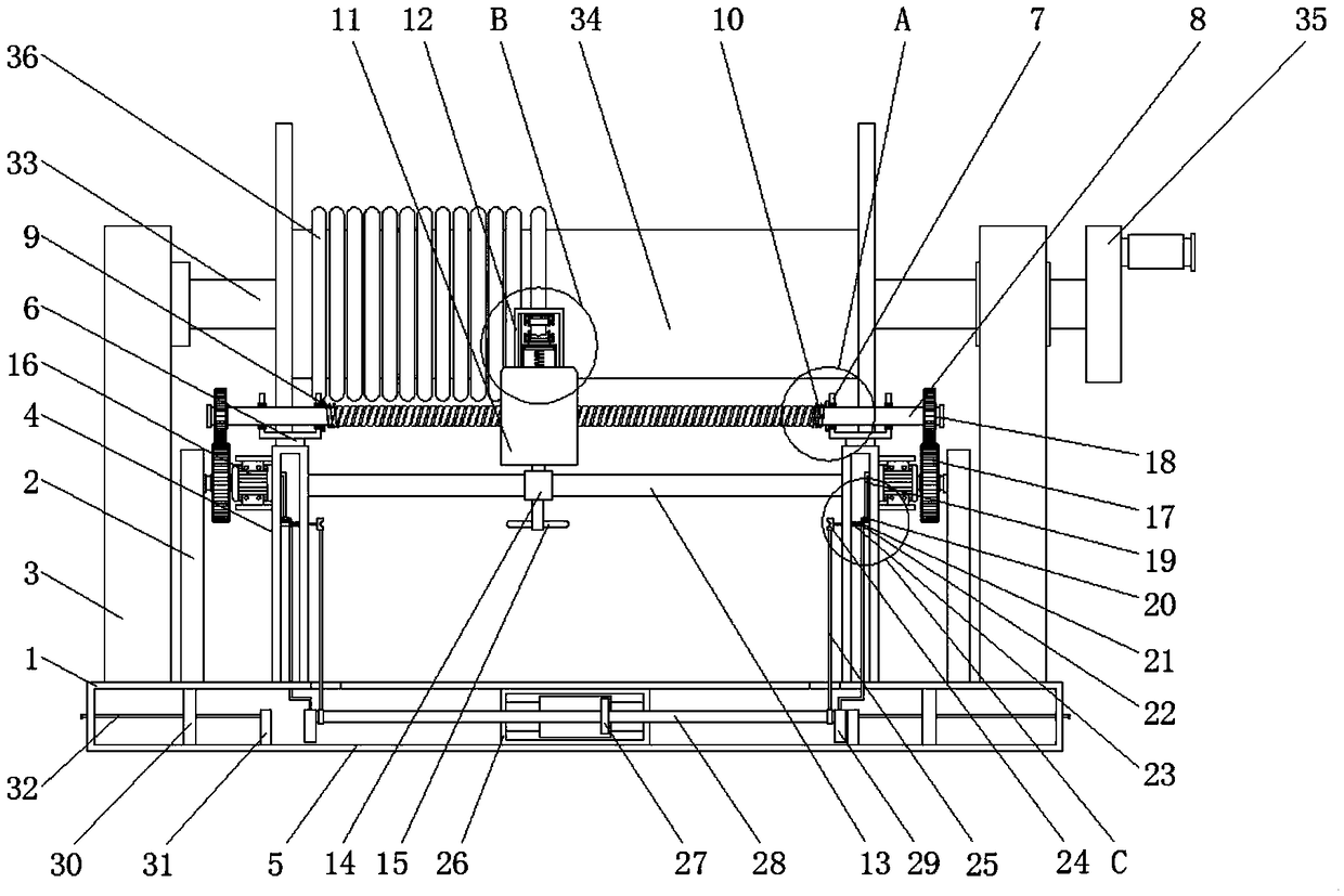
Figure 1 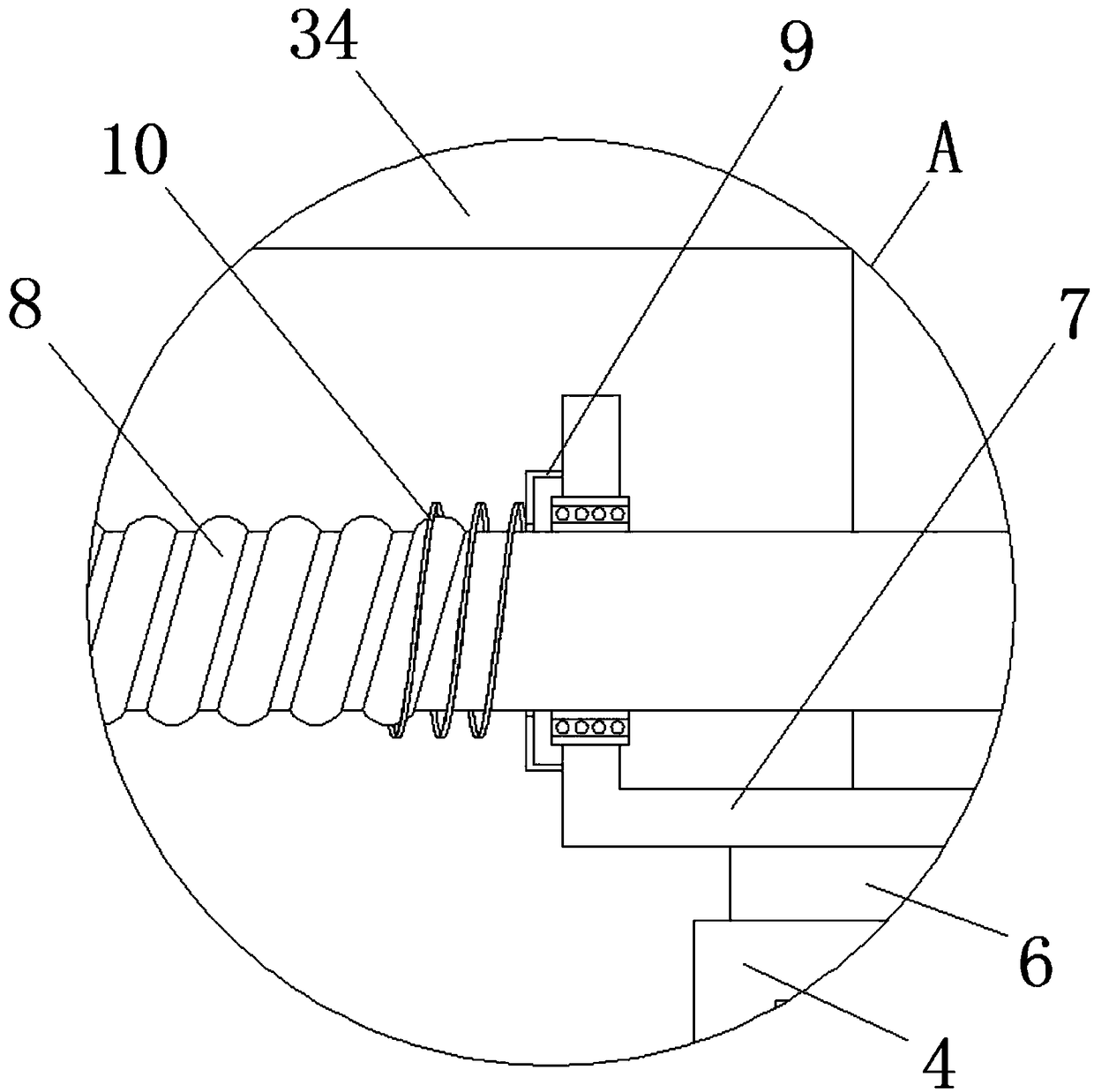
Figure 2 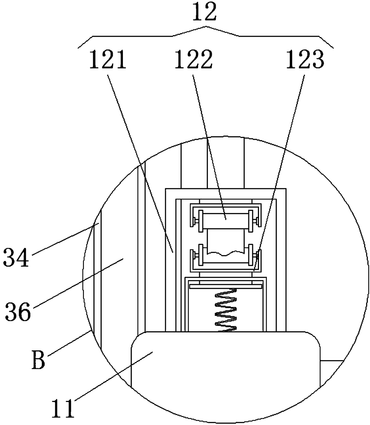
Figure 3
Abstract
Description
technical field
[0001] The invention relates to the technical field of electric wire take-up equipment, in particular to a rewinding and take-up machine for electric wires. Background technique
[0002] Wires refer to wires that transmit electrical energy, including bare wires, electromagnetic wires and insulated wires. Bare wires have no insulation layer, including copper, aluminum flat wires, overhead stranded wires, and various profiles (such as profiled wires, busbars, copper bars, aluminum bars, etc.), which are mainly used for outdoor overhead and indoor busbars and switch boxes. Electromagnetic wire is an insulated wire that generates a magnetic field or induces current in a magnetic field after being energized. It is mainly used for motor and transformer windings and other related electromagnetic equipment. The conductor is mainly copper wire, which should have a thin insulating layer and good electrical properties. Mechanical properties, as well as heat resistance,...
Examples
Embodiment Construction
[0031] The following will clearly and completely describe the technical solutions in the embodiments of the present invention with reference to the accompanying drawings in the embodiments of the present invention. Obviously, the described embodiments are only some, not all, embodiments of the present invention. Based on the embodiments of the present invention, all other embodiments obtained by persons of ordinary skill in the art without making creative efforts belong to the protection scope of the present invention.
[0032] see Figure 1-7 , a wire rewinding machine, comprising an insulating base 1, both sides of the top of the insulating base 1 are fixedly installed with support plates 2, and the two sides of the top of the insulating base 1 are respectively fixedly connected with installations located on the outside of the two support plates 2 plate 3, and the top of the insulating base 1 is fixedly installed with two receiving plates 4 located inside the supporting plate ...