
a turboshaft engine

A turboshaft engine and turbine technology, applied in the field of aviation power systems, can solve the problems of short life of the turboshaft engine, complex turbine structure, high manufacturing cost, etc., and achieve the effects of long processing cycle, improved energy utilization rate, and high manufacturing cost

Active Publication Date: 2020-05-19
HUAZHONG UNIV OF SCI & TECH
View PDF10 Cites 0 Cited by
  • Summary
  • Abstract
  • Description
  • Claims
  • Application Information

AI Technical Summary

Problems solved by technology

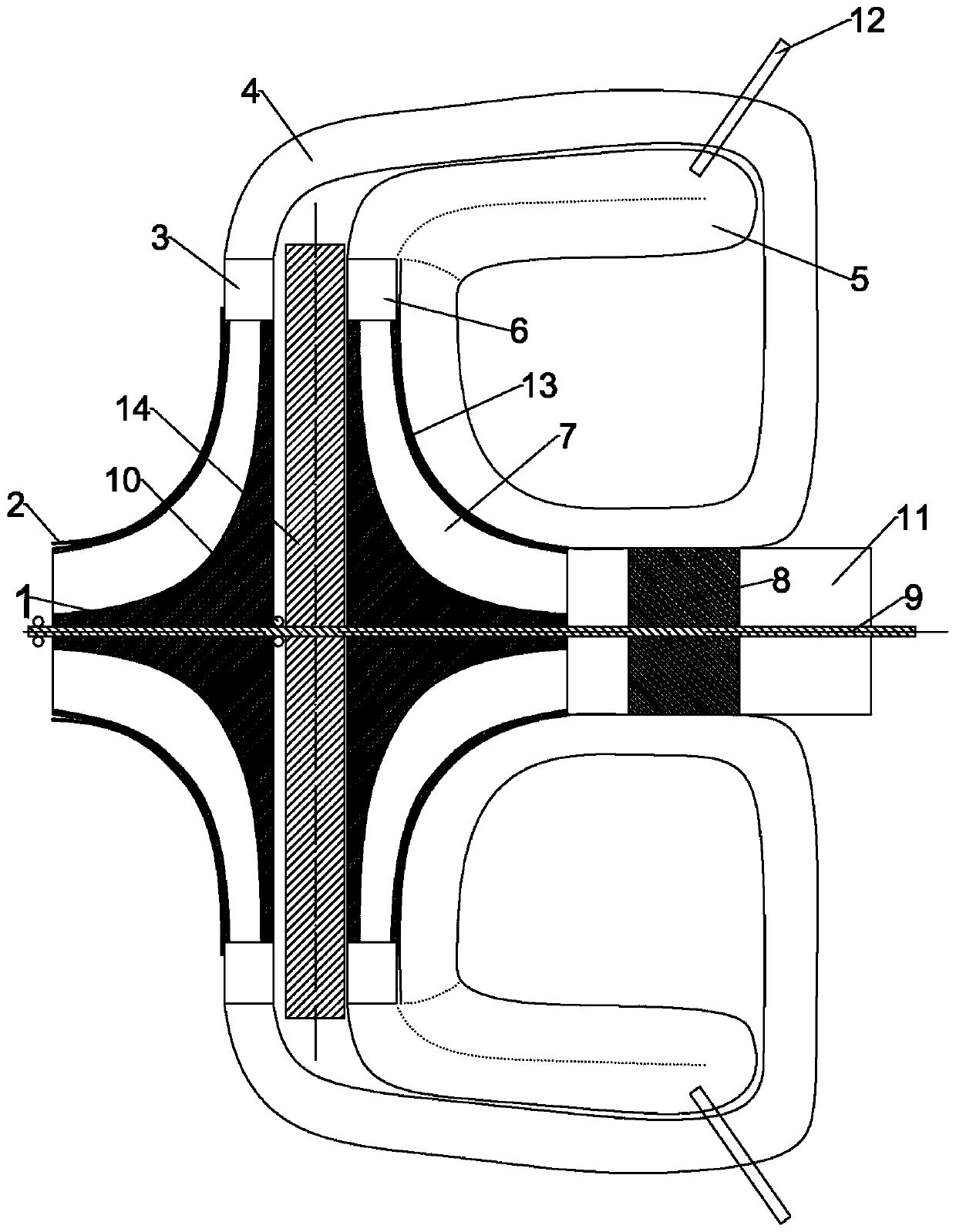
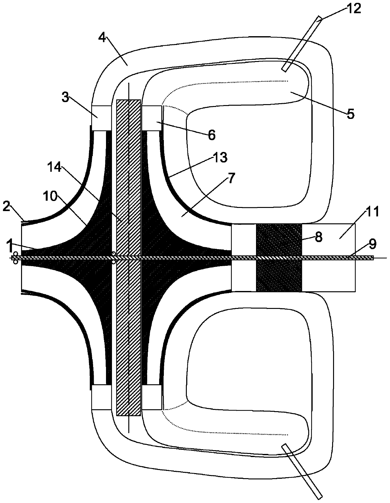
[0007] Aiming at the above defects or improvement needs of the prior art, the present invention provides a high-efficiency turboshaft engine. In the process of returning to the bleed air duct, it not only cools the outer wall of the combustion chamber casing and the outer wall of the turbine cover to improve the life of the return combustion chamber and the centripetal turbine and the gas temperature in the return air bleed duct, but also absorbs the inner wall of the return flow combustion chamber casing The radiated heat also increases the gas temperature in the return-type bleed air duct; moreover, when the return-type bleed air duct exchanges heat with the regenerator, the high-pressure air is further heated, which improves the energy utilization rate and reduces the engine's Fuel consumption rate; solve the technical problems of turboshaft engine with short service life, complex turbine structure, low efficiency, long processing cycle and high manufacturing cost by changing the structure of engine components and the structural layout of flow channels

Method used


Image

  • a turboshaft engine
  • a turboshaft engine
  • a turboshaft engine

Examples


Embodiment Construction

[0034] In order to make the object, technical solution and advantages of the present invention clearer, the present invention will be further described in detail below in conjunction with the accompanying drawings and embodiments. It should be understood that the specific embodiments described here are only used to explain the present invention, not to limit the present invention. In addition, the technical features involved in the various embodiments of the present invention described below can be combined with each other as long as they do not constitute a conflict with each other.

[0035] Such as figure 2 As shown, a high-efficiency turboshaft engine provided by the embodiment of the present invention includes a centrifugal compressor 1, a centrifugal compressor cover 2, a radial diffuser 3, a return-type bleed air conduit 4, a return combustion chamber 5, Adjustable turbine guide 6, centripetal turbine 7, high-efficiency regenerator 8, transmission shaft 9, two air bear...


PUM


Abstract

The invention discloses a high-efficiency turbo-shaft engine, and belongs to the technical field of aviation power systems. The high-efficiency turbo-shaft engine comprises a transmission shaft, a centrifugal compressor, a centripetal turbine, an air exhaust section and an efficient heat regenerator, wherein the centrifugal compressor, the centripetal turbine, the air exhaust section and the efficient heat regenerator are arranged on the transmission shaft in sequence in the axial direction of the transmission shaft, and the efficient heat regenerator is installed in the air exhaust section. The high-efficiency turbo-shaft engine further comprises radial pressure expanders, rectangular-ambulatory-shaped air guide pipes, backflow combustion chambers, adjustable turbine guiders and air bearings. The rectangular-ambulatory-shaped air guide pipes encircle the whole backflow combustion chambers, and the outer walls of engine boxes of the backflow combustion chambers and the outer wall of aturbine cover are cooled through heat exchange. Meanwhile, the heat radiated by the inner walls of the engine boxes of the backflow combustion chambers is absorbed by the air in the rectangular-ambulatory-shaped air guide pipes, the rectangular-ambulatory-shaped air guide pipes and the efficient heat regenerator conduct heat exchange, and therefore the high-pressure air inside the rectangular-ambulatory-shaped air guide pipes can be further heated. According to the high-efficiency turbo-shaft engine, the component structural mode of the engine and the structural layout of a flow channel are changed so that the technical problem that a turbo-shaft engine is short in service life, complex in turbine structure, low in efficiency, long in processing cycle and high in manufacturing cost can besolved.

Description

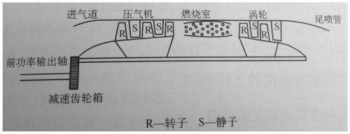
technical field [0001] The invention belongs to the technical field of aviation power systems, and more specifically relates to a high-efficiency turboshaft engine. Background technique [0002] In the field of aviation vehicles, small turboshaft engines are widely used in tilt-rotor UAVs and vertical take-off and landing unmanned helicopters. figure 1 It is a typical structural diagram of a single-shaft turboshaft engine. This diagram can be widely seen in textbooks, such as page 157 of the book "Working Principles and Performance of Aviation Gas Turbine Engines" edited by Shanghai Jiaotong University Press and Zhu Zhili. A schematic diagram of the structure is shown. [0003] The turbine parts of traditional turboshaft engines are mainly composed of turbine rotor and turbine stator, and the turbine rotor is composed of turbine working blades, turbine disks, turbine shafts and connecting parts; the turbine stator is composed of turbine casings, guide vanes and other parts,...

Claims


Application Information

Patent Timeline
IPC IPC(8): F02C7/00F02C7/18F02C7/08F02C7/06F02C3/04F02C3/14
CPCF02C3/04F02C3/145F02C7/00F02C7/06F02C7/08F02C7/18
Inventor 李仁府雷新国熊有德
Owner HUAZHONG UNIV OF SCI & TECH
Learn More