High-airtightness tunnel kiln

A tunnel kiln and high-density technology, applied in the field of tunnel kiln, can solve the problems of increasing airflow resistance, thermal deformation of skirts, difficult to control the quality of fired products, etc., and achieve the effect of good sealing effect.

Pending Publication Date: 2018-11-16
DONGTAI CENT HEAT RESISTANT MATERIALS
View PDF0 Cites 2 Cited by
  • Summary
  • Abstract
  • Description
  • Claims
  • Application Information

AI Technical Summary

Problems solved by technology

Usually, the sealing and isolation system for the bottom of the tunnel kiln includes a curved sealing structure between the lining part of the kiln car and the kiln wall, and a sand seal between the kiln car skirt plate and the sand sealing groove containing kiln sand set on the kiln wall. Sealing structure; in order to improve the sealing effect between the side of the kiln car lining and the kiln wall, usually the side of the kiln car lining and the opposite kiln wall will be made with corresponding uneven surfaces, forming a so-called curved seal structure. Tortuous and relatively narrow gaps are formed from top to bottom to increase airflow resistance and reduce the flow of high-temperature hot air in the working space of the kiln to the bottom. However, in order to ensure the normal operation of the kiln car, prevent thermal deformation of the kiln car lining and kiln wall bending seal The error of the shape and position of the surface of the structure will bring friction obstacles to the operation of the kiln car, and there will still be a large gap be...

Method used


Image

  • High-airtightness tunnel kiln
  • High-airtightness tunnel kiln
  • High-airtightness tunnel kiln

Examples


Embodiment Construction

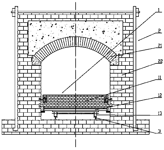
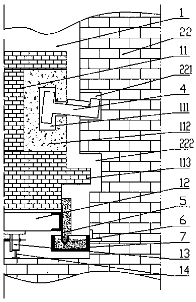
[0028] exist figure 1 In the shown high-sealed tunnel kiln, the kiln wall 22 and the kiln roof 21 constitute the kiln body 2 of the tunnel kiln, kiln rails 3 are laid on the bottom surface of the tunnel kiln, and the kiln car 1 is located between the kiln walls 22 on both sides and runs in the kiln. On the rail 3, the kiln car 1 includes a car frame 12, a wheel 13 rotatably supported on the car frame 12 and located on the kiln rail 3, and a kiln car lining 11 located on the car frame 12. see figure 2 The kiln car lining part 11 is built on the upper surface of the car frame 12 by refractory bricks. The refractory bricks located on both sides of the kiln car lining part 11 include T-shaped groove bricks 112, and several T-shaped groove bricks 112 are along the kiln car lining. T-shaped grooves 111 are arranged in the T-shaped groove bricks 112. In this way, T-shaped grooves 111 are formed on the side of the kiln car lining part 11, and the T-shaped grooves 111 extend from the...


PUM


Abstract

The invention discloses a high-airtightness tunnel kiln. The high-airtightness tunnel kiln comprises a kiln body composed of kiln walls and a kiln top, and a kiln car composed of a car frame, car wheels and a kiln car lining portion and operating on kiln rails. T-shaped grooves are formed in the side surfaces of the kiln car lining portion and formed along the full length of the kiln car. A plurality of packer bricks are movably inserted into the T-shaped grooves correspondingly and arranged in the length directions of the T-shaped grooves in sequence. Packer grooves are formed in the kiln walls correspondingly, and the external extending ends of the packer bricks are movably arranged in the packer grooves correspondingly. Skirt plates are arranged on the side surfaces of the car frame, sand sealing grooves containing kiln sand are formed in the kiln walls correspondingly, each skirt plate comprises a skirt plate body, the lower lateral side of each skirt plate body is connected with asand sealing inserting portion in a groove shape, the upper portion of each sand sealing inserting portion is connected with a skirt plate brick body, and the sand sealing inserting portions are inserted into the kiln sand. By adopting the high-airtightness tunnel kiln, good sealing isolation protection can be formed for the bottom of the tunnel kiln, heat is effectively prevented from being transmitted to the bottom of the tunnel kiln, and in addition, it can be guaranteed that the kiln car operates in the kiln walls without hindrance.

Description

technical field [0001] The invention relates to an industrial furnace, in particular to a tunnel kiln. Background technique [0002] Tunnel kiln is a modern industrial furnace, which has the advantages of continuous production, short cycle, large output, high quality and high efficiency. The main structure of the tunnel kiln is a tunnel structure with two sides of the kiln wall and the kiln roof. A track for the kiln car is laid on the bottom of the kiln. The products to be fired are loaded on the kiln car. From front to back, it is divided into three areas: preheating, firing and cooling. The combustion equipment is set in the middle of the firing area, and the working temperature in between is usually above 1,000 degrees. The products to be fired are carried into the tunnel kiln one by one in front and back, and pass through the preheating area, firing area and cooling area in turn, and the products made are pushed out of the tunnel kiln one by one. Workflow. The kiln w...

Claims


Application Information

Patent Timeline
IPC IPC(8): F27B9/26F27B9/30
CPCF27B9/262F27B9/30
Inventor 朱军朱慧王辉宇崔恒洋朱卫国
Owner DONGTAI CENT HEAT RESISTANT MATERIALS
Why Eureka
Try Eureka